Hi guys!
I have this schematic:

It is parallel ECC82 grounded cathode and 6922 in SRPP. I don't understand, the filter in fb, also can anybody explain how to "reverse engeineer" a shematic and calculate currents and voltages. It's weird, especially SRPP with kind of anode resistor.
Thanks in advance!
I have this schematic:
It is parallel ECC82 grounded cathode and 6922 in SRPP. I don't understand, the filter in fb, also can anybody explain how to "reverse engeineer" a shematic and calculate currents and voltages. It's weird, especially SRPP with kind of anode resistor.
Thanks in advance!
The introductory chapters of Morgan Jones' book titled Valve Amplifiers provide an excellent tutorial on this topic. Judging by the confused hookup around R8, the posted schematic appears to have been rendered by a draftsman rather than an engineer. R10 doesn't seem to belong here at all.
Well , R10 have a high value in this schematic , but you can use it in a SRPP circuit and with a value not greater than R8 , I see this in many SRPP circuit ! , using a value of 22.6 Kohm for R10 will increase the output impedance of the SRPP circuit ! .
But on the other hand , I think the designer , wants to lower more the distortion of the SRPP by choosing a high value for R10 and don't interested too much about the output impedance ! .
Last edited:
So it might be a good idea, to remove it and recalculate the SRPP... Might give a try. Guys at Polish diy forum did this pre in original form and they were impressed.
I must say, that this topology doesn't mąkę too much sense... But it will be an hour to build, so why not? I'll give ya my impressions. 🙂
I must say, that this topology doesn't mąkę too much sense... But it will be an hour to build, so why not? I'll give ya my impressions. 🙂
Very interested!!
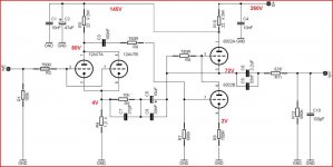
Still don't make much sense. How is the lower 6922 getting plate supply? The plate should be connected the the upper tube cathode, not grid.
The problem is with R8 , R8 should be conected between pin 3 and pin 6 and not between pin 2 and pin 3 .
The schematic is drawn in a confusing way. At first glance it looks like the lower 6dj8 triode does not get a proper anode supply, but it does: The current from the cathode of the upper triode passes through R8 and into the anode of the lower triode, so the two triodes have the same amount of current. Should work OK as it is.
Last edited:
Am I missing something here? It appears to me that the upper 6922 is biased with 0V grid bias. The grid is tied to the cathode with a 750R resistor. What kind of weird sh*t is this. Hoping to learn something new.
Not weird at all. Look carefully at the schematic. The current through the upper triode is the same as the current through the lower triode. There is a voltage drop across resistor R8 which makes the voltage at the grid (upper triode) a couple of volts lower than the voltage at the cathode (upper triode) as it should be. I cannot see any problem, except that the schematic is drawn in an unconventional way which is confusing.
Did you draw this schematics, or found it somewhere?This looks more the way it was ment. Not that I like it very much🙁
Mona
Just changed one connection so it would make sense.Modified some wierd values and checked the working condition of the valves, it can function this way.Did you draw this schematics, or found it somewhere?
Mona

Hi,
A while ago a customer sent me a hand drawn schematic of this lamm pre.
AFAIK, the schematic as posted wasn't what I remember it to be. I'll check it if someone's interested.
Cheers, 😉
A while ago a customer sent me a hand drawn schematic of this lamm pre.
AFAIK, the schematic as posted wasn't what I remember it to be. I'll check it if someone's interested.
Cheers, 😉
That'd be great! 🙂Hi,
A while ago a customer sent me a hand drawn schematic of this lamm pre.
AFAIK, the schematic as posted wasn't what I remember it to be. I'll check it if someone's interested.
Cheers, 😉
- Status
- Not open for further replies.
- Home
- Amplifiers
- Tubes / Valves
- Lamm clone