Hi
Any sugestions of a DIY L-meter using a 0-500Mhz frequency counter?
I´ll need it to work at least in 1-100 Henry range (or more), and with DC bias
I´ll found some diy projects out there, but most in to low Inductance range and no DC-bias
Regards
Pix
Sweden
Any sugestions of a DIY L-meter using a 0-500Mhz frequency counter?
I´ll need it to work at least in 1-100 Henry range (or more), and with DC bias
I´ll found some diy projects out there, but most in to low Inductance range and no DC-bias
Regards
Pix
Sweden
Yes sure, But I was thinking more of a resonant circuit, where I could calibrate the circuit for the freq. counter to display the inductance without calculations and with accuracy
/Pix
/Pix
Unless the coil has a very high Q and low parasitic capacitance you won't get a very sharp peak -- but it can be done that way. Meters like the HP5328 have signal shaping circuitry to help ferret out the peak. Ham radio "Grid Dip Meters" were variable frequency oscillators, you attached a capacitor and swept the frequency until you got a null.
A bridge circuit is pretty easy to build --
A bridge circuit is pretty easy to build --
Attachments
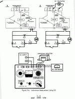
I don't see how that works; it looks as though all it's doing is measuring the dc resistance of the inductor.
To measure inductance, which is defined in terms of rate of change of current, you need a signal that changes with time.
Of course it's easiest to get an inductance bridge, or even one of those old G-R or EICO or Heath impedance bridges. (I have an extra G-R bridge.)
Measuring with a counter will require a variable signal frequency. Getting direct readout is a little more trouble.
Of course it's easiest to get an inductance bridge,
It is a bridge, an ESI 250 Bridge --
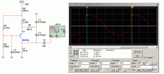
Getting back -- you can make a Colpitts oscillator with just one transistor -- in this case the time interval of 10mS is proportionate to the value of the inductor:
Attachments
Is that bridge circuit doing it ballistically? Close the switch and look for the direction of deflection on the detector?
It ought to be possible to just build an oscillator with the DUT and a few switchable reference capacitors, and read the frequency with the counter.
IMO, a proper bridge circuit and AC source is better because you can get both value and Q. Not hard to build but if you just buy a used GR1650 everything's already done for you, probably with parts better than you can easily buy today. Not sure about the max range- why do you need such a high value?
Oddly, the GR716C capacitance bridge lists measuring extremely high inductance values under "other uses" in the manual. Like MH (not mH), though I've never run across one (MH, not 716C).
My G-R 1650A is a fine instrument, accurate and has a wide range. I don't use it because I have a newer model.
But any inductance measurement must take into account the frequency of operation. If it's intended for high frequency use, an audio frequency measurement is of limited value, and vice versa. In addition, it it's got a ferrous core, the amplitude of the signal and any dc through it are important factors.
But any inductance measurement must take into account the frequency of operation. If it's intended for high frequency use, an audio frequency measurement is of limited value, and vice versa. In addition, it it's got a ferrous core, the amplitude of the signal and any dc through it are important factors.
Oddly, the GR716C capacitance bridge lists measuring extremely high inductance values under "other uses" in the manual. Like MH (not mH), though I've never run across one (MH, not 716C).
How's that 716 web page doing?
The ESI250 has a 1kHz generator, I couldn't find a 1650 inexpensively when I was looking. I've owned some other ESI stuff and it's always been very good.
I've almost finished a rewrite of my 716C web page- just need to take some photos. The GR section is one of the last corners of my site that still needs to be redone. I spent last weekend making new polypropylene insulators for my 716 and got the leakage from 150 megohms to about 30 gigohms. What a pita to change out. Hopefully this coming long weekend I'll be able to calibrate it and do more capacitor testing. So far the skeptic in me thinks no human should be able to tell the difference between most decent caps in a blind test. Still, there are easily measurable differences and the most perfect caps are probably certain ceramics, followed by polypropylene. I'd need more samples to say if Teflon is routinely better or not. At the moment I'd have to say it's not money well spent, unless one is building precision integrators. BTW, Henry Hall, who designed the Digibridge, told me they used Teflon caps in some of those so the first measurement would agree with subsequent measurements.
Inductors are also quite interesting since they're a far less perfect component than caps. Lots of construction compromises one can make with geometry and wire choice. I tend not to use them for audio, only for switching supplies ;-)
Inductors are also quite interesting since they're a far less perfect component than caps. Lots of construction compromises one can make with geometry and wire choice. I tend not to use them for audio, only for switching supplies ;-)
I have one of these, but its to heavy to carry around
I have one of these tube monsters (G-R 650-A):

But the range is limited to 10Henry and 40mA DC bias.
I need at least 100H (preferably 500H) and at least 100mA (preferably 300mA) DC Bias
But mostly, itas to heavy to carry fom my garage to my workshop every time I need to measure inductance


/Pix
Sweden
I have one of these tube monsters (G-R 650-A):
But the range is limited to 10Henry and 40mA DC bias.
I need at least 100H (preferably 500H) and at least 100mA (preferably 300mA) DC Bias
But mostly, itas to heavy to carry fom my garage to my workshop every time I need to measure inductance
/Pix
Sweden
I've almost finished a rewrite of my 716C web page
Conrad -- that reconstructed piece of GR craftsmanship is a thing of beauty!
i've always found it useful to connect a known capacitor across the coil and drive the circuit with a square wave, and look at the ringing frequency on a scope. you can do this with DC bias applied as well. all you have to do is get the frequency of the square wave to about 1/10 the resonant frequency of the cap/coil combination. or you can wire them as a series resonant circuit with the scope across the coil and ramp the frequency of the square wave generator by hand until you find the resonant frequency (much larger peak than with parallel resonant). but with a series resonant setup it's not easy to apply a DC bias to the coil.
- Status
- Not open for further replies.
- Home
- Design & Build
- Equipment & Tools
- L-meter using a 500Mhz freq. counter ?