Relay is cycling. I have pulled R35 and amp stays on. Relay comes on.
I have replaced U14 (LM361) and U11 (TL072C), put R35 back in circuit, get the same results. Cycling protection. Pulling R34 back out now.
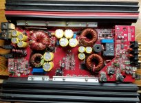
I have board out of chassis. All PS FET's are new 3205's with 47ohm resistors, and 640's and 9640's are new.
I have 12v across all four zeners.
Voltages of IC's
U14 LM361
Pin 1: 12.03
Pin 2: 0
Pin 3: -7.42
Pin 4: -.452
Pin 5: 0
Pin 6: -11.75
Pin 7: 0
Pin 8: 2.76
Pin 9: -1.30
Pin 10: -1.17
Pin 11: 2.31
Pin 12: 0
Pin 13: 2.81
Pin 14: 2.81
U11 TL072C
Pin 1: 10.12
Pin 2: 28.80
Pin 3: 0
Pin 4: -11.75
Pin 5: .556
Pin 6: .560
Pin 7: 5.61
Pin 8: 12
U13 TL072c
Pin 1: .002
Pin 2: .002
Pin 3: 0
Pin 4: -11.75
Pin 5: 0
Pin 6: .007
Pin 7: .625
Pin 8: 12
I have replaced U14 (LM361) and U11 (TL072C), put R35 back in circuit, get the same results. Cycling protection. Pulling R34 back out now.
I have board out of chassis. All PS FET's are new 3205's with 47ohm resistors, and 640's and 9640's are new.
I have 12v across all four zeners.
Voltages of IC's
U14 LM361
Pin 1: 12.03
Pin 2: 0
Pin 3: -7.42
Pin 4: -.452
Pin 5: 0
Pin 6: -11.75
Pin 7: 0
Pin 8: 2.76
Pin 9: -1.30
Pin 10: -1.17
Pin 11: 2.31
Pin 12: 0
Pin 13: 2.81
Pin 14: 2.81
U11 TL072C
Pin 1: 10.12
Pin 2: 28.80
Pin 3: 0
Pin 4: -11.75
Pin 5: .556
Pin 6: .560
Pin 7: 5.61
Pin 8: 12
U13 TL072c
Pin 1: .002
Pin 2: .002
Pin 3: 0
Pin 4: -11.75
Pin 5: 0
Pin 6: .007
Pin 7: .625
Pin 8: 12
Attachments

Last edited:
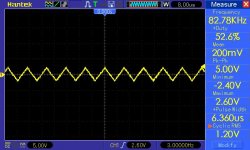
With R35 lifted, jumper from Pin 3-U14-LM361 to signal ground (opposite side of C270-220p). Check for drive at output inductors.
Check U14-Pin 4 then Pin 11 with your scope, using signal ground for scope GND. Post screens shots.
Check U14-Pin 4 then Pin 11 with your scope, using signal ground for scope GND. Post screens shots.

The older Kicker amps are clocked and don't need an input drive signal to produce the drive signal to the output stage. Their class D section is very similar to the one in the following amp.
http://www.bcae1.com/temp/bp1200p1_sm.pdf
Class D - type 1 if you have the tutorial.
http://www.bcae1.com/temp/bp1200p1_sm.pdf
Class D - type 1 if you have the tutorial.
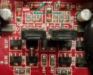
There is a disruption in the feedback loop, check the drivers Q113,Q104,Q135,Q126 and associated components around them, check L105,L106-output inductors and connections.
I found a resistor open R215 120ohm off the collector of Q135. I replaced temp. with a through hole 120ohm resistor. ( don't have a smd 120). Still the same results, pin 4 has a signal, but don't have it on Pin 11. Checked all surrounding components all seem to check good.
I am using a KX1200.1 print it seems to be pretty dang close to it. I dont see the 4.7 ohm resistor off of D116 and R193, it may not even be on this board. But if it was open it may be the problem.
I am using a KX1200.1 print it seems to be pretty dang close to it. I dont see the 4.7 ohm resistor off of D116 and R193, it may not even be on this board. But if it was open it may be the problem.
Attachments
Last edited:
I'm not sure what 4.7 ohm your referring to. D116 and R193 are part of the over current protection.
It's possible Q135 has failed. Check L104 with an ohmmeter, it may be open.
It's possible Q135 has failed. Check L104 with an ohmmeter, it may be open.
Papaz would you happen to know what the voltages on Q135 should be?
I have pulled the transistor and it does check good.
The 4.7 ohm resistor may not even be in this amp
I have pulled the transistor and it does check good.
The 4.7 ohm resistor may not even be in this amp
I don't have any notes handy. Compare the voltages with Q113-A1381. You can also try replace Q135 if you have the part.
Quick question, if I unsolder pin 11 on LM361, should I have a signal then, if there is nothing wrong with the IC
Let me rephrase that question. If I removed all 4 transistors Q104,113,126, and 135. Shouldn't I get a signal on pin 11 of the LM361?
- Home
- General Interest
- Car Audio
- KX750.1