If there was an oscillation, the freq magnitude response would show a peak there.
This all seems quite allright, the increasing phase shift at LF is not unusual because of the various coupling caps in the system.
But the gain has fallen off in that region, so it cannot support oscillations.
No worries.
Jan
This all seems quite allright, the increasing phase shift at LF is not unusual because of the various coupling caps in the system.
But the gain has fallen off in that region, so it cannot support oscillations.
No worries.
Jan
Yes if that's a bode plot that could be an issue. It's a problem as Jan explains of having a lot of coupling caps and the OPT. Often in practice you see the cones of the speakers moving. You may need to create a dominate pole, or some sort of pole zero cancellation. Could you post a schematic.
That's not what I said. The gain does not peak at LF. The cone may move since this amp has an insane and very ill advised freq response down to 1Hz, but it will not oscillate.
Jan
Jan

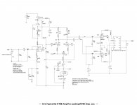
I sent this because it has a different arrangement of feedback components. C1 R10 and R9 form a zero pole cancellation which will help with your LF stability.
Baudouin0,
Thanks for the information. It's the same configuration of what I have except that I use 6SL7 for the input stage and KT88 for output tube. In my case I have to increase the driver stage caps to 4.7u in order to suppress the peak in the 1Hz region. What's frequency response and power output of above amp? Thanks.
Thanks for the information. It's the same configuration of what I have except that I use 6SL7 for the input stage and KT88 for output tube. In my case I have to increase the driver stage caps to 4.7u in order to suppress the peak in the 1Hz region. What's frequency response and power output of above amp? Thanks.
@ baudouin0,
Would you be willing to share some of the models in your trans.lib file (and maybe the symbol files that go with them)? OPT modeling has been the most problematic aspect of tube amplifier simulation for me. I have some models that I have collected over the years but many models claiming to represent the same output transformer can give widely different results, especially in Bode plots. Of course, simulation results are only as good as the models used so this isn't unexpected. But I'm always on the lookout for models that produce results similar to bench testing.
Would you be willing to share some of the models in your trans.lib file (and maybe the symbol files that go with them)? OPT modeling has been the most problematic aspect of tube amplifier simulation for me. I have some models that I have collected over the years but many models claiming to represent the same output transformer can give widely different results, especially in Bode plots. Of course, simulation results are only as good as the models used so this isn't unexpected. But I'm always on the lookout for models that produce results similar to bench testing.
It's dangerous to believe Spice simulations involving output transformers - they're much too primitive. Real OPTs are a moving target whose magnetizing (primary) inductance generally increases with signal level. This, in turn, pushes down that RL pole, very often until it approaches an RC pole that we have depended on to not be dominant (higher in frequency than the OPT's RL pole).In my case I have to increase the driver stage caps to 4.7u in order to suppress the peak in the 1Hz region.
There are conditionally stable solutions using stepped compensation, but you'll have to find them empirically (because the modelling isn't trustworthy) and/or be lucky. The attempt to move the RC pole below the LC pole (4u7F C3 and C4 !) is the wrong direction for this and one other reason. At clipping, the output valves' grids conduct, charging C3 and C4, changing the output valves' bias (more negative). The recovery time constant is a product of C3/C4 and their associated circuit resistances. Much over about a quarter second makes for poor high output performance, quite audible at party levels.
Stability without drama requires a single pole guaranteed to remain dominant at all signal levels, and the classically best place to put it is the RC pole at the output valves' grids. A classic number here, for very good OPTs, is a high pass of about 4Hz. If you look at the design of Golden Age classics, you'll find numbers in this range. A little higher is even better.
All good fortune,
Chris
So some I have measured and adjusted the parameters to match the measurement (such as the 1650T). If done correctly they are quite accurate enough to adjust both the HF and the LF NFB. They are small to medium signal models and are linear. This is fine for checking stability as usually the oscillation starts in the small signal. I would disagree with Chris in that I found them very useful when building a number of amps and the the resulting stability was very similar to that predicted. It does mean measuring up the transformer with the same primary and secondary impedances for gain and phase and adjusting the models to match. I also would expect when the transformer saturates at LF then primary inductance would drop a lot pushing up the pole rather than down. Transformers have improved a great deal over the years and fitting a new transformer to an old design does often means changing the NFB components. Often their dominate pole is nearer 3Hz making it very similar to the inter-stage coupling which is not what you want. I have found the best solution of LF stability is lead lag compensation in the same way its done that HF. If you take data from the data sheet you need the primary inductance at 50Hz or lower but the leakage inductance at 1KHz or higher. You also need the primary capacitance which is just a first order model.
Last edited:
Thanks. I have some of theses models as well but do not know the source of some of them. The Eric Barbour model of the Dynaco A-431 in particular gives simulation results pretty close to actual measurements.
I had not considered lead-lag compensation for the low end but this does seem like something worth exploring. My general approach has been to stagger the interstage time constants so that they don't accumulate phase shift as fast at the extreme low end. I agree with Chris that lowering the output stage time constant (i.e., raising the corner frequency) seems to improve the LF stability margin. Shannon Parks (the creator of the Poseidon Dynaco Mark III driver) gave a good explanation for how to determine that capacitor value empirically in answer to a user question about increasing the capacitance of the RC coupling networks. Here is a link to that discussion, FYI. See Shannon's last post in the thread.
http://www.diytube.com/phpBB2/viewtopic.php?f=2&t=5255
Let me re-phrase my POV, because I think we're not that far apart: The OP is trying to use the RL pole of the output valves' source resistance x the OPT's primary inductance as their dominant pole. I know this because of their comment about increasing C3 and C4 to improve VLF response flatness. This is a dangerous path because OPT primary inductance varies with signal level in a direction that moves that RL pole towards the RC pole(s) as signal level increases (until approaching saturation). The degree of change with signal level varies with core material, etc. but the trend is always in the same direction.
If the RL pole is designed to be dominant, stability decreases with increasing signal. If an RC pole is designed to be dominant, stability increases with increasing signal. Make it stable at idle, and it will be stable at all levels, and without needing esoteric knowledge of the OPT's details.
There are also the separate issues of blocking distortion and the OPT's finite ability to handle subsonics gracefully, and both argue for smaller rather than larger C3 and C4.
All good fortune,
Chris
- Home
- Amplifiers
- Tubes / Valves
- KT88 Amp Phase & Gain & Stabilization Plot in LTspice