Hello Friends
Looking for some help on Krell KSA 50 Feedback adjustment.
I was trying to adjust the bias on my Krell KSA 50 (not MK2) and adjusted feedback trimmer/potentiometer instead as there is only one trimmer on the board and I thought that was the bias trimmer. I am assuming its feedback circuit but not sure. Looks like someone has replaced the bias trimmer with a fixed resistor as shown in the picture or it might be fixed from the beginning. I didn't notice that and turned the available trimmer for bias adjustment. It was not doing anything and I turned it in all different directions as its not responding. And unfortunately I did the same on both left and right channels otherwise I would have some reference measurements from the other one.
Amp is working fine but not sure if the feedback is messed up now and would cause any issues after some time.
Looking for help on How to measure and adjust this feedback back to the correct level again. Or is it just look for any audible distortion and adjust to eliminate it. I have a multimeter only and not any other equipment
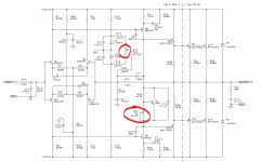
Attached a circuit found on the web which very closely matches with my amp
Thank you
cv
Looking for some help on Krell KSA 50 Feedback adjustment.
I was trying to adjust the bias on my Krell KSA 50 (not MK2) and adjusted feedback trimmer/potentiometer instead as there is only one trimmer on the board and I thought that was the bias trimmer. I am assuming its feedback circuit but not sure. Looks like someone has replaced the bias trimmer with a fixed resistor as shown in the picture or it might be fixed from the beginning. I didn't notice that and turned the available trimmer for bias adjustment. It was not doing anything and I turned it in all different directions as its not responding. And unfortunately I did the same on both left and right channels otherwise I would have some reference measurements from the other one.
Amp is working fine but not sure if the feedback is messed up now and would cause any issues after some time.
Looking for help on How to measure and adjust this feedback back to the correct level again. Or is it just look for any audible distortion and adjust to eliminate it. I have a multimeter only and not any other equipment
Attached a circuit found on the web which very closely matches with my amp
Thank you
cv
Attachments
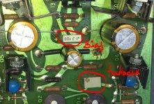
That is not feedback trimmer, but the output DC offset. It is easy to check.
Just disconnect the input, and output connections. Set your DC voltmeter to the output terminals, and set the output voltage as close to 0V as possible.
Few mV is no problem.
Just disconnect the input, and output connections. Set your DC voltmeter to the output terminals, and set the output voltage as close to 0V as possible.
Few mV is no problem.
Hello sajti,
Thank you so much for looking into my post and educating and helping me. This is my first post and very happy to see a response to this and so quickly. Internet is so wonderful 🙂
I think I can do what you've advised. So basically I will connect multimeter to speaker terminals and adjust this trimmer to see close to 0V DC.
The reason I wanted adjust the bias in the first place is finding different temperatures on each channel on the heat sink at idle. Then I thought the bias is not in sync on these two channels. Then I measured voltages across emitter resistors (0.5 ohms each not 0.68 as shown in the circuit). There are 4 pairs of output transistors. Two pairs for each channel.
Here are measurements
Left channel - Pair1 - bias voltage across Emitter Resistors - 540mv
Left channel - Pair2 - bias voltage across Emitter Resistors - 510mv
Right channel - Pair1 - bias voltage across Emitter Resistors - 495mv
Right channel - Pair2 - bias voltage across Emitter Resistors - 480mv
Not sure why the voltages are different within pairs in one channel itself as they are controlled by a single fixed bias resistor?
Should I replace the fixed 5k resistor shown in the picture with a trimmer to adjust the bias and make it equal on both channels.
Sorry for too many questions.
Thank you and appreciate your help
I would not change the bias. It should be 500mV, as i know. The asymmetry between the pairs will not change with bias settings.