Hello! I'm a newbie to this forum so I apologise if this isn't the right place to put this thread, and also for my lack of experience 😅
I'm no electrical engineer, just someone in their late teens without too much experience in vintage audio so any guidance / help would be appreciated on this 🙂
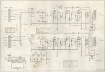
I've been super intrigued by valve amps for a little while now but I've been a bit picky and quite a cheapskate up to this point too 😅 I finally decided to dive in headfirst last week and picked up a Kontakt KT-7 Single Ended integrated from around 1967, Japanese made and sold in the Netherlands, in working condition but in need of a good service. There are a couple of variants out there but mine is the original 5 valve model (2x EL84, 2x 12AX7 and an EZ80 rectifier) without the additional MM phono stage and luckily I have access to a full schematic which I found online (Also attached below).
For it's age the amplifier is still surprisingly working alright, but the tone controls feel very non-linear with only a very small sweet spot and otherwise the music ends up sounding very shrill or very dull. It is manageable and I can still get the amp to sound just right but my biggest gripe at the moment is some audible background interference / hiss heard when there's nothing playing. It isn't 50hz / 100 hz humming and it does change with the volume control, if that helps 😅
All I've done for now is given the potentiometers some Deoxit fader lube and checked for any cold / corroded solder joints to no result. This amp still has all of it's original capacitors aside from two which seem newer than the rest (The 2 red WIMAs between the pre / power valves) and I intend on replacing the lot of them, one section at a time before I do any proper heavy listening with the amp. That's all fine and well, I've ordered some replacement parts from Mouser and they'll be in the UK within a few days but until then I find myself staring at the schematics and looking into the amp confronted with a new problem - the way the grounding is wired up. I don't have many complaints about the wiring of it as it does seem to be done as per the schematic, but it looks like one of the speaker terminals is being used as a star ground point (yikes!) and a lot of the design relies on the tag boards and their respective centre pins being soldered directly to the chasis for mounting meanwhile doubling up as a ground path, with the original main ground point (I believe) being at the 265v HT centre tap. At one point it looks like a previous owner has replaced whatever the original power lead was with a 3-core mains cable and has screwed down / soldered the earthing conductor to the chasis as you'd expect, but the original schematics don't have any reference to a CPC / earthing terminal and it doesn't look like this amp was designed with that kind of earthing in mind whatsoever. I'm not sure what Japanese / Dutch electrical standards at the time were like, but it makes me think that the "new" (Well, newer) earthing / grounding arrangements could be responsible for causing said interference on the amp, especially since it can change depending on what other appliances are plugged in / being used around the house.
I've looked into adding a grounding bus that would be connected back to the centre tap and it would be a possible modification for this amplifier without too much extra work so that the dependance on the chasis for ground could be addressed. I'm not ruling out the possibility that my interference issue could be caused by something else / an issue that gets solved during the recap, but at the very least it's an improvement I have in mind. I'm pretty happy with how I'd go about doing most of it, but I'm a bit stumped when it comes to the secondary side of the OPTs as some people claim the common (black / - speaker wires) wires must be grounded too for safety reasons. That's all fine by me and I understand the reasons for why this is done, but I've also heard claims that with a single ended setup like in my case, it's an optional choice to make and that it can affect the sound, etc etc etc.
So all of my rambles aside, here's my newbie question:
Whether I'd like to do it or not, I'm just wondering should I connect the common speaker terminals directly to the chasis earth point or to the power transformer's centre tapped ground? Assuming that they were no longer connected to one another by the chasis. And if I were to connect my hypothetical grounding bus in order of: centre tap > PSU / coupling caps > EL84 > 12AX7 > RCA terminals, where should the OPT common wire be connected between in that case? If not on the grounding bus, then just directly to the chasis earth wire? Please let me know your thoughts! 🙂
Photos of the amp attached below:


The OPT secondary wires should be as follows:
16 Ohm - White
8 Ohm - Yellow
Common - Black
And supposedly the blue severed ones are unused connections for a 4 Ohm tap that may have been intended for other amp models
Sorry for the poor-ish quality of the photos, but hopefully they're good enough to give a general idea, at least! Also take note of the black wires which all tend to go towards the grounded centre pins of the tag boards (Also yes, I do intend to touch the mains wire points up too once I start properly working on this thing. That cable tie is naaaasty)
Thanks for reading! 🙂
I'm no electrical engineer, just someone in their late teens without too much experience in vintage audio so any guidance / help would be appreciated on this 🙂
I've been super intrigued by valve amps for a little while now but I've been a bit picky and quite a cheapskate up to this point too 😅 I finally decided to dive in headfirst last week and picked up a Kontakt KT-7 Single Ended integrated from around 1967, Japanese made and sold in the Netherlands, in working condition but in need of a good service. There are a couple of variants out there but mine is the original 5 valve model (2x EL84, 2x 12AX7 and an EZ80 rectifier) without the additional MM phono stage and luckily I have access to a full schematic which I found online (Also attached below).
For it's age the amplifier is still surprisingly working alright, but the tone controls feel very non-linear with only a very small sweet spot and otherwise the music ends up sounding very shrill or very dull. It is manageable and I can still get the amp to sound just right but my biggest gripe at the moment is some audible background interference / hiss heard when there's nothing playing. It isn't 50hz / 100 hz humming and it does change with the volume control, if that helps 😅
All I've done for now is given the potentiometers some Deoxit fader lube and checked for any cold / corroded solder joints to no result. This amp still has all of it's original capacitors aside from two which seem newer than the rest (The 2 red WIMAs between the pre / power valves) and I intend on replacing the lot of them, one section at a time before I do any proper heavy listening with the amp. That's all fine and well, I've ordered some replacement parts from Mouser and they'll be in the UK within a few days but until then I find myself staring at the schematics and looking into the amp confronted with a new problem - the way the grounding is wired up. I don't have many complaints about the wiring of it as it does seem to be done as per the schematic, but it looks like one of the speaker terminals is being used as a star ground point (yikes!) and a lot of the design relies on the tag boards and their respective centre pins being soldered directly to the chasis for mounting meanwhile doubling up as a ground path, with the original main ground point (I believe) being at the 265v HT centre tap. At one point it looks like a previous owner has replaced whatever the original power lead was with a 3-core mains cable and has screwed down / soldered the earthing conductor to the chasis as you'd expect, but the original schematics don't have any reference to a CPC / earthing terminal and it doesn't look like this amp was designed with that kind of earthing in mind whatsoever. I'm not sure what Japanese / Dutch electrical standards at the time were like, but it makes me think that the "new" (Well, newer) earthing / grounding arrangements could be responsible for causing said interference on the amp, especially since it can change depending on what other appliances are plugged in / being used around the house.
I've looked into adding a grounding bus that would be connected back to the centre tap and it would be a possible modification for this amplifier without too much extra work so that the dependance on the chasis for ground could be addressed. I'm not ruling out the possibility that my interference issue could be caused by something else / an issue that gets solved during the recap, but at the very least it's an improvement I have in mind. I'm pretty happy with how I'd go about doing most of it, but I'm a bit stumped when it comes to the secondary side of the OPTs as some people claim the common (black / - speaker wires) wires must be grounded too for safety reasons. That's all fine by me and I understand the reasons for why this is done, but I've also heard claims that with a single ended setup like in my case, it's an optional choice to make and that it can affect the sound, etc etc etc.
So all of my rambles aside, here's my newbie question:
Whether I'd like to do it or not, I'm just wondering should I connect the common speaker terminals directly to the chasis earth point or to the power transformer's centre tapped ground? Assuming that they were no longer connected to one another by the chasis. And if I were to connect my hypothetical grounding bus in order of: centre tap > PSU / coupling caps > EL84 > 12AX7 > RCA terminals, where should the OPT common wire be connected between in that case? If not on the grounding bus, then just directly to the chasis earth wire? Please let me know your thoughts! 🙂
Photos of the amp attached below:
The OPT secondary wires should be as follows:
16 Ohm - White
8 Ohm - Yellow
Common - Black
And supposedly the blue severed ones are unused connections for a 4 Ohm tap that may have been intended for other amp models
Sorry for the poor-ish quality of the photos, but hopefully they're good enough to give a general idea, at least! Also take note of the black wires which all tend to go towards the grounded centre pins of the tag boards (Also yes, I do intend to touch the mains wire points up too once I start properly working on this thing. That cable tie is naaaasty)
Thanks for reading! 🙂
Attachments
Last edited:
The speaker common should go to the power supply common. Never leave it floating.
In this unit the use of feedback does require that it be grounded.
The tone circuit is passive, and you can just bypass it if you don't want to use it.
That will give you 6dB more gain, and so reduce the relative noise level for the input stage.
Replacing some of the carbon composition resistors may help reduce the noise.
At least check their values, since they can drift a lot.
The low voltage cathode bypass capacitors often degrade and need replacement.
Last edited:
I see. Thank you! Just to clarify, in this hypothetical case I would want to skip the ground bus and take it directly to the centre tapped point on the mains transformer, is that right? It sounds like a rather obvious question but just to be certain 😛The speaker common should go to the power supply common. Never leave it floating.
In this unit the use of feedback does require that it be grounded.
The tone circuit is passive, and you can just bypass it if you don't want to use it.
That will give you 6dB more gain, and so reduce the relative noise level for the input stage.
Replacing some of the carbon composition resistors may help reduce the noise.
At least check their values, since they can drift a lot.
The low voltage cathode bypass capacitors often degrade and need replacement.
I'm glad you've confirmed that the tone circuit can be bypassed too! Another modification I'm thinking of is adding an additional pair of RCA jacks to do that just for purist's sake, but I'll try and get a solid foundation with this amp first before getting any more ideas ahah
Thanks for the tip about those resistors too! for what it's worth, I've measured most of them with one leg clipped and they're all still mostly within their tolerances but some of them are certainly asking to be replaced sooner or later. I'll have to look more into that once I sort out the re-capping. My capacitor tester is a cheap multi-purpose component tester that can't detect DC leakage so even though a lot test reasonably I'm starting off the refurb with those. Decent quality replacements aren't going to break the bank, fortunately. Thank you for your time! I really appreciate it 😀
I usually ground it close to the stage serving as input for global negative feedback, if GNF is used. Otherwise, as said above, just ground it at the the power supply common.
Theoretically, if everything is done exactly right, the ground reference should be at the input socket.I usually ground it close to the stage serving as input for global negative feedback, if GNF is used. Otherwise, as said above, just ground it at the the power supply common.
However, this is not practical to do in most cases.
Indeed, I seem to recall that grounding the input socket is not good for stereo amps.Theoretically, if everything is done exactly right, the ground reference should be at the input socket.
However, this is not practical to do in most cases.
I see. Thank you! Just to clarify, in this hypothetical case I would want to skip the ground bus and take it directly to the centre tapped point on the mains transformer, is that right?
I'm glad you've confirmed that the tone circuit can be bypassed too! Another modification I'm thinking of is adding an additional pair of RCA jacks to do that just for purist's sake, but I'll try and get a solid foundation with this amp first before getting any more ideas
In this circuit, connect the secondary return wire directly to the common lead of the power supply
capacitor that is labeled "A" to minimize the hum.
You could add a switch to short between input and output to bypass the tone circuit,
instead of adding an extra set of input sockets.
Yes, that can cause hum. Used to be routinely done in mono days, when it didn't.Indeed, I seem to recall that grounding the input socket is not good for stereo amps.
You have not replaced the 60+ year (and lowest-bidder) old B+ filter caps, and you have buzz?This amp still has all of it's original capacitors
Do that first.
It is possible this amp had a little buzz when new. Think like a 1962 salesman. There would also be a 15W and a 35W model at higher prices and, just to justify that price, lower residual buzz. But it didn't buzz enough to make you look at another brand.
It is folly to think you know more than the guys who built these things for a living. Star/bus/taxi/galactic grounding theories have their places in new construction, but are easier to get wrong than right, and often can't be retro-fitted to existing amps without a bulldozer and ground-up rebuilding.

- Home
- Amplifiers
- Tubes / Valves
- Kontakt KT-7 ~ Grounding Conundrum!