Hi.
So, since I have nothing better to do besides make amplifiers, I'm making another one-- this time it's the Aikido-based Tetra Sans using all 12AT7 tubes.
I'm working through the circuit now with the intent of powering it using the Broskie PS-1 power supply.
The manual is more than a little confusing to me in some places, so I wanted to ask if anyone has experience with this configuration and could advise on the following:
1. The manual indicates that the ideal value for the "Raw B+" is 340 volts. The PS-1 only outputs 300 volts, so I'm hoping I can work with that voltage. Has anyone implemented the Tetra / PS-1 / 12AT7 combo that could advise?
2. The manual indicates that the ideal value of the "B+ at tube" is 250V. If I assume that this is the recommended B+ value at the plate, wouldn't this only be for one tube (perhaps the one nearest the B+)? If so, it's not clear to me what I should expect at the plates for each of the hour 12AT7s. Any ideas?
I'll be working through the circuit this weekend and will likely have to adjust B+ as I go, but any guidance anyone could offer on target B+ and plate voltage would be much appreciated.
Thanks,
Kofi
A buddy of mine built one with 12AT7 and another tube, I forget which. He used a PS1 as well at about 315 volts if memory serves. It worked well for him but was a bit thin in the bass for his tastes. He prefers his Bottlehead phono stage but it is noisier. I think if he did a bit of tube rolling Tetra he'd get the sound he likes.
Hope this helps, Steve
Hope this helps, Steve
The manual quotes an acceptable range of 250V - 400V, so 300V will be fine.1. The manual indicates that the ideal value for the "Raw B+" is 340 volts. The PS-1 only outputs 300 volts, so I'm hoping I can work with that voltage.
Yes it is at the plate of the cathode follower part of the tube. You can see the label "B+" on the diagrams in the manual. That's the node Broskie is ambiguously referring to.2. The manual indicates that the ideal value of the "B+ at tube" is 250V. If I assume that this is the recommended B+ value at the plate, wouldn't this only be for one tube (perhaps the one nearest the B+)?
Last edited:
A buddy of mine built one with 12AT7 and another tube, I forget which. He used a PS1 as well at about 315 volts if memory serves. It worked well for him but was a bit thin in the bass for his tastes. He prefers his Bottlehead phono stage but it is noisier. I think if he did a bit of tube rolling Tetra he'd get the sound he likes.
Hope this helps, Steve
Thanks. I think I saw a post where someone found the bass to be lacking, but then upped the value of the coupling caps and the bass improved. I'll be using some 2.2uF Auricaps I have laying around, so I'm hoping that would be more than enough for good bass response.
The manual quotes an acceptable range of 250V - 400V, so 300V will be fine.
That's what I thought, but I just needed someone to confirm.
Yes it is at the plate of the cathode follower part of the tube. You can see the label "B+" on the diagrams in the manual. That's the node Broskie is ambiguously referring to.
Got it. Makes sense. Just trying to follow the Broskie logic through the manual and getting a bit lost.
I'm assuming if I elect NOT to include R9 for the optional high frequency correction then I also do not need to include C9 || C10, correct?
Kofi
You still need C9/C10 to complete the RIAA correction. When he says 'leave out' R9 he actually means jumper it, not leave it open circuit.If I elect NOT to include R9 for the optional high frequency correction then I also do not need to include C9 || C10, correct?
You still need C9/C10 to complete the RIAA correction. When he says 'leave out' R9 he actually means jumper it, not leave it open circuit.
Wow. There's no way I would have understood that based on the manual. Thanks for clearing that up.
Kofi
Yes, the manual could be a bit more user friendly... 🙄Wow. There's no way I would have understood that based on the manual.
Finished the preamp today and I'm amazed by how quiet it is. I have the power supply right next to the tetra sans circuit and there is no hum whatsoever.
It's very detailed and, unfortunately, it has confirmed that my current phono preamp (Steve Bench's RIAA) has an oscillation issue that is generating some sibilance.
It does not seem to have quite the same depth as the Bench RIAA, however it's still early and I haven't finished tweaking / breaking in yet. I'm also thinking that the four 12AT7s may be a bit too much gain, so I'm thinking of swapping two of them out for a 6DJ8 front end.
Overall, it sounds wonderful. I'll be listening quite a bit tonight and will update on modifications and observations.
Kofi
Wow, no drama with accompanying humorous tales of bleak devastation. It almost makes me sorry you succeeded, but I'm very pleased you did. 😀
Parts Value
Can you please confirm the following parts value C4,C15,C17,C11,R12, and did you use any line stage with Tetra Sans Ps ?
Finished the preamp today and I'm amazed by how quiet it is. I have the power supply right next to the tetra sans circuit and there is no hum whatsoever.
It's very detailed and, unfortunately, it has confirmed that my current phono preamp (Steve Bench's RIAA) has an oscillation issue that is generating some sibilance.
It does not seem to have quite the same depth as the Bench RIAA, however it's still early and I haven't finished tweaking / breaking in yet. I'm also thinking that the four 12AT7s may be a bit too much gain, so I'm thinking of swapping two of them out for a 6DJ8 front end.
Overall, it sounds wonderful. I'll be listening quite a bit tonight and will update on modifications and observations.
Kofi
Can you please confirm the following parts value C4,C15,C17,C11,R12, and did you use any line stage with Tetra Sans Ps ?
Wow, no drama with accompanying humorous tales of bleak devastation. It almost makes me sorry you succeeded, but I'm very pleased you did. 😀
I feel the same way. Don't worry-- I'll screw up again soon. I still have a power amp to tweak.
Can you please confirm the following parts value C4,C15,C17,C11,R12, and did you use any line stage with Tetra Sans Ps ?
I did not use a line stage-- plenty of gain from the preamp and loads of power from my Uniamp II.
I wouldn't mind revealing those values, only I'm wondering if Broskie left those values off his published documents for a reason. Since it's his design and he's clearly selling boards and kits based on it I'm not sure if it would breach the tenets of the diyAudio world if I revealed them.
Again, I'd be glad to do it, but I don't want to anger the diyAudio gods. They damn you with parasitic oscillations and untraceable hum when they're angry.
Anyone care to weigh on on whether these values should be considered public domain or not? Am I being over-cautious?
Kofi
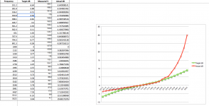
OK-- so I've noticed that I seem to be getting a lot of sibilance with the Tetra Sans (measured vinyl tracks against corresponding iPod tracks and the difference is sibilance!). I set up a little test lab with a multimeter, an Online Tone Generator and a spreadsheet containing dB gain / loss values I found from Hagerman Technologies.
I used the dB levels he provided for his inverse RIAA as the basis for the dB steps I should get with the Tetra Sans. I played a test tone through my mac and into the RIAA and recorded the change in voltage, which I converted to a dB change with the 1K voltage as the V0 reference (20*(log(v1 / v0))) and noticed that my RIAA looks jacked up.
Here's a screen grab of the dB actual vs. target and the discrete values. It seems unlikely to me that it's THIS off, so I'm guessing I'm measuring wrong somehow.
Any help would be appreciated.
Kofi
Attachments
What values did you end up using for C7/8/9/10, R7/8, and what tube types?
An ordinary multimeter may give innacurate readings for frequencies other than 50/60Hz. Also, are you sure you're not overdriving the phono input?
An ordinary multimeter may give innacurate readings for frequencies other than 50/60Hz. Also, are you sure you're not overdriving the phono input?
Last edited:
For c7/c8 I have about .1uF and for c9/c10 I have something around .0340uF. R7 is about 22.1k and r8 is about 3.18k. All 12at7s.
For testing I was able to get the inputs down to about 5.4 mc. That's why I used the laptop. I was able to get the voltage lower when using my Mac for signal input.
OK-- so I've noticed that I seem to be getting a lot of sibilance with the Tetra Sans (measured vinyl tracks against corresponding iPod tracks and the difference is sibilance!). I set up a little test lab with a multimeter, an Online Tone Generator and a spreadsheet containing dB gain / loss values I found from Hagerman Technologies.
I used the dB levels he provided for his inverse RIAA as the basis for the dB steps I should get with the Tetra Sans. I played a test tone through my mac and into the RIAA and recorded the change in voltage, which I converted to a dB change with the 1K voltage as the V0 reference (20*(log(v1 / v0))) and noticed that my RIAA looks jacked up.
Sibilance might be from your phono cartridge. I've noticed the same issue with some records.
The RIAA phono amp boosts the base and reduces the treble. During record cutting, the bass is reduced to minimize the swing of the cutter. The treble is boosted to increase the signal over the surface noise of the record. During playback, the bass is boosted back up, the treble back down.
Easiest way to measure is to build his reverse RIAA circuit and plug it into your phono amp. Set a signal generator to get a reasonable output for your true RMS multimeter and sweep from 20Hz to 20kHZ. The reading should stay close to constant across that range.
Sheldon
Last edited:
Sibilance might be from your phono cartridge. I've noticed the same issue with some records.
The RIAA phono amp boosts the base and reduces the treble. During record cutting, the bass is reduced to minimize the swing of the cutter. The treble is boosted to increase the signal over the surface noise of the record. During playback, the bass is boosted back up, the treble back down.
Easiest way to measure is to build his reverse RIAA circuit and plug it into your phono amp. Set a signal generator to get a reasonable output for your true RMS multimeter and sweep from 20Hz to 20kHZ. The reading should stay close to constant across that range.
Sheldon
You know, that's exactly what I thought. So I actually bought the inverse RIAA from Hagerman with the intent of doing just that. Then I put it somewhere in the house. And now it's gone.
Kofi loses things.
Anyway, I'm working on the cartridge as well. It's a brand new Denon DL 103r. I've added some weight to the headshell and installed the Michell Technoweight to my Rega RB250 on my Thorens TD160. With the new counterweight things are much improved but I am also thinking about repotting it in a Paradox body, but the Technoweight may not have enough mass.
I'll report as I make progress. Thanks for the replies.
Kofi
In principle, you can just print out the correction curve from somewhere like this: RIAA Equalization
Then plot your actual gain curve of input/output (in dB) on the same graph. The problem is that the curve covers a range of 40 dB. With digital gear, it depends on the resolution. Still, if you measure input vs output at each point along the curve, you'll see if you are close.
Sheldon
Then plot your actual gain curve of input/output (in dB) on the same graph. The problem is that the curve covers a range of 40 dB. With digital gear, it depends on the resolution. Still, if you measure input vs output at each point along the curve, you'll see if you are close.
Sheldon
In principle, you can just print out the correction curve from somewhere like this: RIAA Equalization
Then plot your actual gain curve of input/output (in dB) on the same graph. The problem is that the curve covers a range of 40 dB. With digital gear, it depends on the resolution. Still, if you measure input vs output at each point along the curve, you'll see if you are close.
Sheldon
Thanks. That's what I thought I was doing in my earlier post. If you look at my measurements it looks like I'm way off, but I don't think I could be that far off. MerlinB suggested that my Rat Shack multimeter might be at fault since its accuracy may depend on a 60Hz frequency. If you look at my attachment above you can see how whacked out my measurements are.
I realize this thread is a bit old.... however, if you are still tinkering with this trying to tweak for optimum performance, or for the benefit of others that have landed here as a result of a search with a similar issue: the RIAA circuit is no place to be "about" .1uF, "something around....". Precision is required here. 1% resistors are easily enough obtained, however capacitors are a different story. Either get precision capacitors or get a lot of extra capacitors and measure to get a matching pair (for each channel) of correct value. it is for this reason than Mr. Broskie included in the instructions, a chart, on what the values of C9/C10, R7, R8 should be based on the value of C7/8 ranging from .099uF to .1006uF (in .0001uF increments). it is also the reason that all RIAA capacitors and resistors in his board design allow for "trimming" to get very accurate combined values. If the board was ordered along with all of the resistors and capacitors from the Glassware site then most likely you should be OK, although a little bit of measuring wouldn't hurt. Enclosure temperature should also be considered. Allow for adequate cooling! Capacitors can change in value very slightly with temperature change. Film and foil types have better temperature stability. Also as stated earlier: R9 is optional, and if not used, a jumper should be fitted in it's place.For c7/c8 I have about .1uF and for c9/c10 I have something around .0340uF. R7 is about 22.1k and r8 is about 3.18k. All 12at7s.
I have built this phono stage using the PS-1 power supply, 12AT7 as the input stage (@280V), and 6DJ8/6922 as the output (@240V). NOTE: this is not achievable with the board as supplied. I made a small modification to supply the voltage. As supplied the output stage will have more voltage than the input. This should make little, if any difference provided you follow the recommended voltages for the tube type. Without modification using the tube combination I used: use the 6922 as the input and the 12AT7 as the output. I can assure you that sibilance is NOT inherent to this design. My phono stage is very musical, and has excellent frequency response, producing very deep tight bass, and extended (not emphasized) treble. Soundstage and articulation are superb. it is also very quiet, allowing a lot of low level detail to come through. Comparing the same tracks; .flac file digital to my analogue setup: bass, mids, and treble are equal in terms of response, however my analogue is treble is less hard (shrill, fatiguing), and mids just seem to have a sense of better realism. IMHO you'd need to spend a great deal more $$ for any commercial offering to be half as good, and the quality of the circuit board is superior to any I've seen, kit, or commercial. As offered, board only, or with any components you would like, it offers a great deal of flexibility. Your choice of tubes (input and output), a little positive feedback, or cathode resistors bypassed (or not). use your own component values, or follow the recommendations as outlined in the instructions: this is for the novice, and the expert. It will require a step-up device (transformer or active amplification stage) for LOMC use. Definitely worthy of consideration for anyone looking for a DIY MM phono stage or MC with step-up device.
Just my $0.02, YMMV. Just thought I'd share my own personal experience with this particular product.
Abe
- Status
- Not open for further replies.
- Home
- Amplifiers
- Tubes / Valves
- Kofi's Tetra Sans