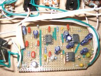
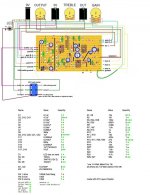
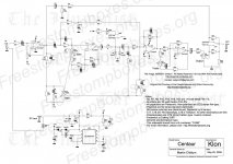
I built this pedal for my son for a Christmas present and it doesn't work. I've included the schematic, layout and picture. It does not pass audio and it has a oscillating, chirp type sound when I turn up the gain knob. I've checked the IC pin voltages and noticed IC2 pins 1 and 7 are to low. These are the output pins of the TL072. I'm using a 9vdc, 300mA wall wart and the voltage unloaded is 13.6vdc. Here are the IC pin voltges:
IC1
1 - 6.02
2 - 6.02
3 - 4.66
4 - 1mV
5 - 6.03
6 - 6.04
7 - 6.04
8 - 12.17
IC2
1 - 2.2
2 - 5.75
3 - 6.06
4 - (-11.7)
5 - 6.04
6 - 6.04
7 - 3.8mV
8 - 22.3
IC3
1 - 12.6
2 - 5.89
3 - 1.8mV
4 - (-5.96)
5 - (-11.68)
6 - 7.61
7 - 10.09
8 - 12.16
Here is a link to another build and the correct pin voltages:
freestompboxes.org • Login
This is my first vero board build. There were quite a few trace cuts but I've double checked with my DMM that they were correct. I've also double checked component placement and orientation, but I'm going to check again. If someone has the time to look this over and maybe have an idea about what I did wrong it would be much appreciated. Thanks.
Tom
Attachments
Well, I've taken out IC2 and all the voltages seem to be right. I've replaced IC2 TL072 with three different ones and I still get low voltage readings on pins 1 and 7. I've checked all the voltages, +V, -V, +V2 and +Vb coming out of the 7660 and up to IC2 and they seem right. I just tried turning all the pots fully open, CW, and the voltage readings on both IC1 and 2 are just jumping all over the place. When I remove IC2 with the pots fully CW the voltages are stable.
Tom
Tom
Last edited:
Hi , can you post voltages referred to GND of +V, -V, +V2 , +Vb ...
Something strange with design ,assuming a 9Vdc regulated supply then:
V+ should be +9V
V+b 4,5V
V- at -9V
V+2 at 18V
So , IC1 supply by single voltage at 9Vdc so is right biasing the non inverting input at middle voltage from Vb ..
Ic2 supply is +18(pin8) and - 9 (pin4) ... and the bias is at 4.5V , how can this work?
IMHO you can supply IC2 from +18(v+2) and GND and put bias at V+ (9V) or (better solution)supply IC2 by + 9V and - 9V and bias to GND ...
Really don't get sense about that circuit design , bad traced or work bad, and the fact so many on freestomp boxes post bad results made me thinking...
Anyway check voltages and post results . Check also connections to the double pot used for GAIN , since it's double a wiring error can occour
Also try don't use that kind of wires ,too much capacitive coupling between wires ,use single wires is better and shielded wires for input and ouput...
P.S: Stupid question...do you plug something at input during test? an open input is always a bad thing for test , plug an instrument with volume at 0 muted or a dummy plug (10k for example) or a shorting plug ...
Happy New Year
Thanks Tesla88, I get to that as soon as I get home from work. Just wanted to say that there have also been quite a few people that have built this and it worked from the start. I'm pretty careful about my wiring but I will definitely change type of wire and then re-measure voltages, with a dummy load input.
Tom
Tom
- Status
- Not open for further replies.