Hi to Everyone, total Noob here but willing 🙂
This is the amp i had sitting in my garage for a long time, taken out of working well sound system.
Decided to power it up before gifting to family member, to test its ok, but when powered up went in protection mode. Worth mentioning i saw a trail of ants coming in and out of it a while before then, gave it a good shake and put in a safe area , when opened amp up there were traces of ant only in the casing of the amp itself, couldnt find any traces on the board itself, ( i will look again when board removed from the case.
Problems.
Protection mode
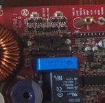
C35 was blown with hole in the middle of it.
R36 looks a like its seen some heat, and has complete continuity (0.01) when checked with ohmeter and beeps in diode mode.
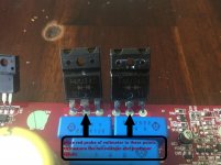
Applied power for a little bit and the two “transisotor” i think get hot. ( marked with two white X’s on the picture.
This is a starting project and a challenge for myself to get it running.
“Work done” :
Replaced c35 with ( what i worked out was a similar capacitor but ended up twice the size of original one ) which i removed as im doubting its a good replacement.( pic atached)
Also checked the 2 rectifiers power supply side ( which after lots of reading on “ basic amplifier repairs website ” seem to check out but im also doubting myself on that one as wel.
Album — Postimage.org
Hopefully link works for the pics, and i thank you for any advice.
This is the amp i had sitting in my garage for a long time, taken out of working well sound system.
Decided to power it up before gifting to family member, to test its ok, but when powered up went in protection mode. Worth mentioning i saw a trail of ants coming in and out of it a while before then, gave it a good shake and put in a safe area , when opened amp up there were traces of ant only in the casing of the amp itself, couldnt find any traces on the board itself, ( i will look again when board removed from the case.
Problems.
Protection mode
C35 was blown with hole in the middle of it.
R36 looks a like its seen some heat, and has complete continuity (0.01) when checked with ohmeter and beeps in diode mode.
Applied power for a little bit and the two “transisotor” i think get hot. ( marked with two white X’s on the picture.
This is a starting project and a challenge for myself to get it running.
“Work done” :
Replaced c35 with ( what i worked out was a similar capacitor but ended up twice the size of original one ) which i removed as im doubting its a good replacement.( pic atached)
Also checked the 2 rectifiers power supply side ( which after lots of reading on “ basic amplifier repairs website ” seem to check out but im also doubting myself on that one as wel.
Album — Postimage.org
Hopefully link works for the pics, and i thank you for any advice.
Last edited:
PapaZBill will be able to help when he sees this.
The resistor (100 ohms) and the capacitor are part of a snubber network and are very unlikely to cause the amp to go into protect, even if out of the circuit.
To upload photos click the following. This will make the photos to others who may need them, even if you delete the photos from your account.
Go Advanced
Manage Attachments
Browse
Upload
Repeat as necessary
Preview post to see how the post will look.
Click Submit Reply to send it to the forum.
B32621A6222K000 EPCOS / TDK | Mouser
The link above will direct you to the replacement capacitor for C35 in the snubber circuit.
You will need to remove R36-100 Ω 3 Watt resistor from the circuit to accurately measure it with an ohmmeter.If the value is more than 10% out replace it.
D12-FMU34S & D13-FMU34R The rectifiers you referred to are most likely okay. If you followed Perry's BCAE, you should read them like a diode between middle to outside leads and shorted or continuity outside to outside leads in circuit.
The transistors Q104-C3503 and Q113-A1381 you marked X are in the output drive circuit, and are getting hot for any number of reasons which most likely is the reason the amp is in protection mode.
When you say protection mode is the protection LED solid red or flashing? Make a careful note what happens when you power the amp up, such as any delays when the LED turns red, slow or rapid on and off flashing of the LED or solid on.
What test equipment including DVM/VOM do you have? What are you using to power up the amp? Do you have a test tone source or generator?
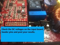
Remove all the outputs IFR9640's (Q109,Q110,Q111,Q131,Q132,133) IRF640's (Q118,Q119,Q140,Q141). This should allow you to power up the amp and make some basic checks such as rail voltages and the +/- 15 volts that are the operating voltages for the opamps on the Preamp/Input board. Be sure to read Perry's BCAE concerning Power Supplys and recommendations on safely powering an amp. You may won't to add low ohm/ high watt resistors in line with the Positive Battery terminal to limit current to safely power the amp and avoid damaging the amp power supply.
All DC voltage measurements should be taken with the black probe of Volt meter placed at the Battery Ground Terminal. Use the pics I edited as a guide.
The link above will direct you to the replacement capacitor for C35 in the snubber circuit.
You will need to remove R36-100 Ω 3 Watt resistor from the circuit to accurately measure it with an ohmmeter.If the value is more than 10% out replace it.
D12-FMU34S & D13-FMU34R The rectifiers you referred to are most likely okay. If you followed Perry's BCAE, you should read them like a diode between middle to outside leads and shorted or continuity outside to outside leads in circuit.
The transistors Q104-C3503 and Q113-A1381 you marked X are in the output drive circuit, and are getting hot for any number of reasons which most likely is the reason the amp is in protection mode.
When you say protection mode is the protection LED solid red or flashing? Make a careful note what happens when you power the amp up, such as any delays when the LED turns red, slow or rapid on and off flashing of the LED or solid on.
What test equipment including DVM/VOM do you have? What are you using to power up the amp? Do you have a test tone source or generator?
Remove all the outputs IFR9640's (Q109,Q110,Q111,Q131,Q132,133) IRF640's (Q118,Q119,Q140,Q141). This should allow you to power up the amp and make some basic checks such as rail voltages and the +/- 15 volts that are the operating voltages for the opamps on the Preamp/Input board. Be sure to read Perry's BCAE concerning Power Supplys and recommendations on safely powering an amp. You may won't to add low ohm/ high watt resistors in line with the Positive Battery terminal to limit current to safely power the amp and avoid damaging the amp power supply.
All DC voltage measurements should be taken with the black probe of Volt meter placed at the Battery Ground Terminal. Use the pics I edited as a guide.
Attachments
Last edited:
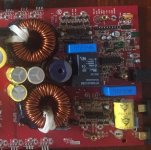
GZinc, when you post pictures, as Perry Babin suggested, please include tighter shots like the two cropped photos I edited. Be sure to take good quality photos without any shadows and flashes that will obscure parts locators and so that any damage to parts or the board can be easily spotted. Perry has some photography tips, using a cellphone or inexpensive digital cameras. I believe you can find them on the BCAE website, if not he may chime in here and point you in the right direction.
Attachments
- Status
- Not open for further replies.