I got this amp from a guy who never saw any signs of life out of it. The only thing he said is someone told him the remote circuit was bad but he didn't seem to know what he was talking about so i took it with a grain of salt.
Shows no visual signs of life, no power or protect .
All power supply FETs have been removed and tested around 200-600 ohms on at least one combination of legs and put in the trash pile.
What I assume are the gate resistors for the power side all read 150 Ohm (as marked) and all from the output side read 22k Ohm (as marked) the large ceramic resistors read .1 Ohm (as marked)
Now, my multimeter( Extech 410 ) on diode check gives me a reading of ohms, not volts. Not sure what is going on there but it’s the only one I have... or ever have had.
TIP35C one per channel x4 read:
“Diode check”:
RED on 1:
2: 809
3: 813
BLACK on 1:
2: climbs to open in about a second (open = 1)
3: 1028
Pins 2 and 3 combinations:
BR 1606
RB climbs to open over about 3 seconds
*(on a new TIP35C my multimeter reads:
*810 BLACK on 1, RED 2 and 3.
OPEN with RED on 1, BLACK on 2 and 3 )
When I removed one 35C from the board it reads the same as a new one.
The place where the 35C was (Q312) reads in ohms:
PIN 1-2 80K Ohm Red to black. But slowly climbs up and up when black to red to open
PIN 1-3 40K Ohm Black to Red. But slowly climbs up and up when Red to Black to open
PIN 2-3 53.5K Ohm Black to Red. But slowly climbs up and up when Red to Black to open
TIP36C: all 4 read the same thing but with leads reversed, except for the channel where the 35C was removed.
This 36C (Q314 photo 1) reads "good" compared to a new one. OPEN / OPEN and 810 / 810
I have not removed any other bipolar transistors from the output side yet besides the one TIP35C
TIP41C and TIP44C (one each) in the power side of the board read defective in the circuit.
There are 1 TIP41C and 1 TIP44C per output channel than read fine in the board.
There is a resistor that comes from right in front of the remote terminal (R4 in photo 6) to a different part of the board climbs slowly from 0 Ohms up and up. When i removed it from to board it tested fine at 20K Ohms (as marked)
I get 12.5 (same as source) over B+ and GND
I get 12.5 from GND to middle leg of power supply fets
I can only get 0 Ohms between RCA ground and negative speaker terminals between channel 1 and 2 RCAS (none for 3 and 4) and Negative speakers terminals for channel 1,2 and 3. (i assumer i removed the 35C from channel 4)
The TL494CN after I took out the power transistors: (black on chasis ground)
1; .2
2; .7
3; 0
4; 0
5; 0
6; 0
7;0
8;.5
9;0
10;0
11;.7
12; 1.2
13; .6
14; .6
15; .4
16; 3.8
I immediately unhooked it after. The next day I came back to it, I tightened up a connection of a small capacitor (C43 photo 6) right in front of the B+ terminal) and must have really messed something up because now I get:
1; 0
2; 0
3; 0
4; 0
5; 0
6; 0
7;0
80.1
9;0
10;0
11;0.1
12; 0
13; 0
14; 0
15; 0
16; 3.8
I’m not really sure what to try next.
Thank you for looking!
Attachments
-
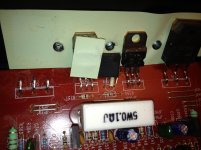 photo (1).jpg644.1 KB · Views: 85
 -
 photo (2).JPG780.3 KB · Views: 103
 -
 photo (3).JPG763.9 KB · Views: 91
 -
 photo (4).JPG746.9 KB · Views: 93
 -
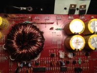 photo (5).JPG577.3 KB · Views: 73
 -
 photo (6).JPG619.8 KB · Views: 53
 -
 photo (7).JPG504.5 KB · Views: 57
 -
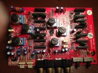 photo (8).JPG837.3 KB · Views: 84
 -
 photo (9).JPG438 KB · Views: 52
Last edited:
- Status
- Not open for further replies.