Hello, I am a newb and was hoping for some help. I'll be the first person to say I am not the greatest with electronics, but I know basics. I have a old KX1200.1 (I have 3 of these amps) One day one of my amps stopped working. No output to sub. I bench tested it with same result. No protection light, (Green light comes on, and relay clicks on) I opened up the amp and looked around didnt see anything obvious. I did notice a little sub board where the RCA's come in (has the 3 little adjustment knobs on it), I took that board out and found some corrosion where the 5 pin connector meets the main board, I cleaned it up, and still no good. I took apart one of my good amps and swapped in a known good sub board. Turned it back on and the amp works perfect. So its not a issue with the main board. I suspected it was something with the RCA inputs, I ohm checked them all from top to bottom of the boards and they look ok, but after that I don't know where else to look. I also noticed that if I use the "Amp Strapping input" as a source the amp works fine.
Any help is greatly appreciated, thanks!
Any help is greatly appreciated, thanks!
Attachments
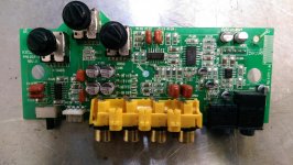

Several things to look for. The first is C123. It opens leaving little or no audio output.
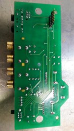
The second is a burned trace leading to the shields of the RCAs very near where JA01 is printed on the board.
There is a trace that leads from R116 that passes under the potentiometer next to it. The frame of the pot sometimes shorts to that trace.
The last thing is the frame leg of one of the pots trying to drive itself through the case of one of the filter capacitors under the board.
Thank you for your response, I spent about a hour closely looking at the 4 areas you mentioned above, and to my eyes and with my cheap meter and my kids magnifying glass they all look good. I wouldnt know how to repair a trace anyway but they look good. I just kept ohm checking from each point to point. I was hoping for something easy like a cracked solder or something. I don't know what else to do. Is there anyone on here that does in-expensive repairs? Could I send it to you to check out? Thanks again,
Jeff
Jeff
I'm not currently taking any repairs that have to be shipped to me.
Do you want to continue troubleshooting?
Do you want to continue troubleshooting?
Sure, I can try. like I said I don't have to much knowledge on this especially the terminology and probably not the best test equipment. But yea that would be great, thanks!
Jeff
Jeff
If you haven't done so already, read the basic amp repair page (all of it - link in sig line below). That will help with some of the most common terminology.
You'll need to be able to power up the amp, drive a signal into it and measure the voltage at various points. Do you have enough equipment to do that?
You'll need to be able to power up the amp, drive a signal into it and measure the voltage at various points. Do you have enough equipment to do that?
Yup, I was kind of doing that last night but getting lost, I had 2 amps both being bench tested side by side and trying to see where I was loosing the signal at.
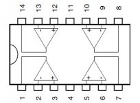
The output pins are the corner pins on the TL074s. Which of those pins have audio and which do not.
Did you try working the switch back and forth with a speaker connected to see if that allowed audio to pass (possibly intermittently) to the main board?
Did you try working the switch back and forth with a speaker connected to see if that allowed audio to pass (possibly intermittently) to the main board?
I checked both TL074 chips on all 4 corners, I am seeing audio outputs on all 8. I toggled the on/off switch several times, I do hear a "click" type noise though the speaker when the switch moves, also if I touch my finger to the VC pin (one of the 5 pins going down to the main board) the speaker also makes a "click" type noise. I tried gentlelly wiggling things around and messing with the potentiometers to see if I can get any noise and I cant seem to get anything. I also wanted to state the application in case that may make a difference. This Amp was in a boat for (8 years) and did see some moisture. Also I had poor grounds. I did see some corrosion on the 5 pin (upper and lower) side, that I tried cleaning off.
I appreciate you helping me diagnose this,
I appreciate you helping me diagnose this,
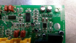
Do you have audio on pin 9 of U103?
See attached, if the red circle indicates Pin 9 of U103, then yes I do have audio there. I wasn't to sure how the pin orientation is Left to Right, Up and Down etc.
Attachments
Ok, I double checked that, and I do not have audio at pin 1. I checked the one diagonally across and no audio. I got a .055v (AC) reading.
How does that compare to the voltage you read on the TL074s?
Do you have the same AC voltage on both terminals of C123?
Do you have the same AC voltage on both terminals of C123?
How does that compare to the voltage you read on the TL074s?
Do you have the same AC voltage on both terminals of C123?
Perry, I made a mistake. I rechecked the TL074s (all the corner pins) and I DO NOT have audio there, I was not checking it correctly. I also have the same voltage on both terminals of C123. The corners of the TL074's are reading the same as pin 9 of U103 & C123 (all reading roughly .050~.055v AC)
Sorry for wasting your time, I am a super amateur to this kind of stuff and I appreciate you walking me through this.
With no music playing it reads .050, when music is on its bouncing around .062~.115 on either the R or L channel of the center terminal.
Download and use the 100HZ test tone. Drive 1/2v into the amp (measured on the RCA jack). Recheck all outputs from the TL074s as well as pin 9 of the 13600 and both terminals of C123.
http://www.bcae1.com/temp/test tones/
Set the crossover to the highest frequency. If it has a subsonic filter set it to the lowest frequency or off. Set the gain to the maximum setting.
http://www.bcae1.com/temp/test tones/
Set the crossover to the highest frequency. If it has a subsonic filter set it to the lowest frequency or off. Set the gain to the maximum setting.
Download and use the 100HZ test tone. Drive 1/2v into the amp (measured on the RCA jack). Recheck all outputs from the TL074s as well as pin 9 of the 13600 and both terminals of C123.
Index of /temp/test tones
Set the crossover to the highest frequency. If it has a subsonic filter set it to the lowest frequency or off. Set the gain to the maximum setting.
Ok, I downloaded the file, and was getting .580v @ the back of the RCA jacks. Also adjusted everything. I didn't know how to determine the difference between the TL074's so see attached.
red TL074
1 .065
2 .065
3 .065
4 .065
blue TL074
1 .065
2 .065
3 .290
4 .290
The only inputs that changed were pins 3 & 4 of the blue TL074
c123 both pins read .054
Pin 9 of U103 is .065
(Not sure what a 13600 is?)
Attachments

The op-amps have circuit board designations silk-screened near them. They are U101 and U102. U103 us the 13600.
I'm assuming that you know that you have to have the board in the amp and the amp powered up.
Confirm that you have at least 0.5v on the back of the RCA jack. Then measure the AC voltage on pins 3 and 5 of U101.
I'm assuming that you know that you have to have the board in the amp and the amp powered up.
Confirm that you have at least 0.5v on the back of the RCA jack. Then measure the AC voltage on pins 3 and 5 of U101.
Attachments
- Status
- Not open for further replies.
- Home
- General Interest
- Car Audio
- Kicker KX1200.1 No output w/ Pics