Bought this amp hooked it up and instantly went in and out of protection while making a ticking noise. I took it apart in my lab and realized one power supply fet was hot. The fet tested bad so bought 3 new Fets for power supply. Checked the UC3843B and found the following on the pins with Fets out:
pin 6 and had the same pulses on gate pad of mosfet
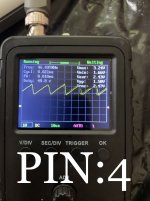
pin 4 sawtooth
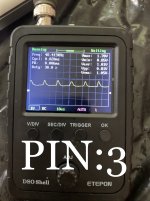
pin 3 similar sawtooth but has 1.7 volts.
pin 8 5.5 volts
My thought is pin 3 should be below 1 volt for operation and followed the trace to Q4 transistor which tested bad. Have t replaced Q4 as I’m not sure this is the true problem. When power supply fets were in I had 60ish positive rail voltage at outputs, can’t remember exact number. Totally thrown off here with this amp.
pin 6 and had the same pulses on gate pad of mosfet
pin 4 sawtooth
pin 3 similar sawtooth but has 1.7 volts.
pin 8 5.5 volts
My thought is pin 3 should be below 1 volt for operation and followed the trace to Q4 transistor which tested bad. Have t replaced Q4 as I’m not sure this is the true problem. When power supply fets were in I had 60ish positive rail voltage at outputs, can’t remember exact number. Totally thrown off here with this amp.
Attachments
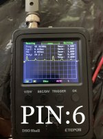
The Drive pulse on Pin 6 is wrong. Are the screenshots taken before or after you replaced the PSMN3R5-80PS Mosfets?
Typically when the PS Mosfets fail, Q5-2045ES should be replaced and may be why the drive is off.
Measure the DC voltage for all Pins of the UC3843 and post.
Typically when the PS Mosfets fail, Q5-2045ES should be replaced and may be why the drive is off.
Measure the DC voltage for all Pins of the UC3843 and post.
The screenshots are with the PSMN3R5-80PS out.
The following are the voltages for UC3843 with MOSFETs out:
Pin1- 7.8 volts
Pin2- 1.2 volts
Pin3- 1.03 volts
Pin4- 2.43 volts
Pin5- 0 volts
Pin6 - pulses from .06 to 7 volts
Pin7 - 10.83 volts
Pin8 - 5.4 volts
The following are the voltages for UC3843 with MOSFETs out:
Pin1- 7.8 volts
Pin2- 1.2 volts
Pin3- 1.03 volts
Pin4- 2.43 volts
Pin5- 0 volts
Pin6 - pulses from .06 to 7 volts
Pin7 - 10.83 volts
Pin8 - 5.4 volts
Replace Q5-2045ES and check the gate resistors 33ohm and 1ohm. Replace Mosfets-PSMN3R5-80PS and recheck.
The triangle wave looks nominal but the drive from Pin 6- UC3843 should be a short duration squarewave.
The triangle wave looks nominal but the drive from Pin 6- UC3843 should be a short duration squarewave.
I replaced the UC3843 also and still have the same issue. After looking at the Datasheet for 3843 I still believe pin 3 should be at or below 1 volts for the internal current sense comparator to work.
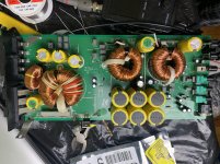
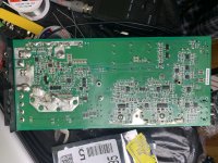
Post a good quality pic of the board.
The problem is most probably in the output . Once I have a pic I can more readily guide you through troubleshooting.
The problem is most probably in the output . Once I have a pic I can more readily guide you through troubleshooting.
You are right about Pin 3 of the UC3843. I believe that the output or housekeeping supplies may be the reason why it is high.
You can check the DC voltages on Pins 1(Vdd) &2(CSD) of IC14 and IC15.
Check DC voltages around Q21 and ZD3,ZD4,ZD5.
Probe Pins 3 & 5 of IC11 for a sawtooth waveform.
All referenced to Power Ground. Post your results and screenshots.
Posting a pic will allow me to edit and point out testpoints etc. Also,I will be able to determine which of the Revs you have. Newer versions use a Microcontroller for the protection circuitry, older versions use an LM339.
The voltages on the IC’s are within tolerance, however the zener diodes are flucting with the protection circuit.
Check D33 and D34-1N4148 if one is shorted replace and install any outputs or PS mosfets if necessary and power up amp as you have been.
If the amp is still in and out of protection, remove D18-1N4148 and recheck.
D33,D34 are tied to the outputs, back to protection,IC17-P7. Shorted D33 or D34 are common problems. D18 is tied to the NTC, and if this brings the amp out of protection there may be a problem with a resistor tied to the IC which is a common failure.
Look for R71-383K ohm and R69-100K ohm. They create a voltage divider for over voltage (OVP) or under voltage protection (UVP), I don't recall which.
Relowing the solder to both resistors may do the trick, but I would recommend replacing both resistors, for a more reliable fix.
As I said this is a common problem, but it's possible something else, such as the IC17-LM339 has failed, but I'm fairly certain the problem is in the voltage divider.
Relowing the solder to both resistors may do the trick, but I would recommend replacing both resistors, for a more reliable fix.
As I said this is a common problem, but it's possible something else, such as the IC17-LM339 has failed, but I'm fairly certain the problem is in the voltage divider.
- Status
- Not open for further replies.
- Home
- General Interest
- Car Audio
- Kicker CXA1200.1 Goes In & Out of protection