Hi. I have a KA-405 that didn't work on the right channel when I got it. I traced through and found that one of the HA1457W amplifier chips had blown. This I replaced, and both channel's signals now appear at the power amp board - but still no R channel output from the power amp board. I found that both output transistors (2SA1105 and 2SC2580) in the R channel had blown. I replaced these, and voila! It worked! … for 30 seconds. There was then a lot of smoke, and both the output transistors had blown again, along with the 2SC1567 NPN driver, and R36, R42 and R46 had burned out, quite spectacularly. I removed the faulty output transistors, replaced the NPN driver and resistors, and checked the voltages on the board, comparing them with the working channel. All seemed ok, and no other devices had blown. Thinking I must have inadvertently shorted something during testing, I replaced the output transistors, and in trepidation switched on. Exactly the same thing happened again. I can't face checking every single component on the board until I know there's no other option; so I wondered if anyone has any advice, or, even better, has come across this problem before? Any help gratefully received.
Many thanks.
Many thanks.
Moved to Solid State forum 🙂
The HA1457W's are just small signal opamps in the front end. The main power amps are fully discrete.
First suspect has to be the series diode network that controls biasing. I'm not a fan of fixed bias and this arrangement relies very heavily on replacement semiconductors having the correct characteristics.
In the first instance I would suggest replacing the diodes with just three series connected small signal types such as 1N4148's and retesting. You can even short those four diodes out and run at zero bias as a test.
Always use a dim bulb tester... it will save fried output transistors.
The diode connected to R42 should be replaced as well.
Attachments
KA-405 smoke
[sorry - posted this first in wrong place!]
Hi mooly. Thanks for your very helpful reply.
I did suspect the diode bias chain, as it seemed that what might be happening was that the output transistors were being driven into thermal runaway. But the diode chain checked out on a component tester, and with the output transistors out of circuit there was a voltage of about 2.1V across it (the same as that across the one in the working channel). I did also replace the diode connected to R42. Is it simply as you say that the bias point is hugely device characteristic dependent? In which case, using three diodes as you suggest and thus reducing the bias current could be a permanent solution? I will certainly try that. When you say 'dim bulb tester' I am not sure what you mean by that! Can you clarify?
Thanks also for the diagram - it is a bit clearer than the one I have (someone, somewhere must have a better copy of the manual? Many of the voltages are unreadable!). Thank you again mooly.
Bulb tester is just a 60 or 100 watt domestic mains filament lamp in series with the mains. If there is a fault then the current rises, the filament resistance increases and the bulb lights. If the current is low, the filament stays cool and appears as a low resistance allowing fairly normal operation of the amp.
If the diode bias theory proves good then ultimately you need to come up with a reliable solution to set the quiescent current correctly... which is easy to do once the basic fault is fixed.
Manual was from HiFiEngine
Kenwood KA-405 - Manual - Stereo Integrated Amplifier - HiFi Engine
If the diode bias theory proves good then ultimately you need to come up with a reliable solution to set the quiescent current correctly... which is easy to do once the basic fault is fixed.
Manual was from HiFiEngine
Kenwood KA-405 - Manual - Stereo Integrated Amplifier - HiFi Engine
OK 🙂
(and remember you can short those diodes out as a test... all other things being equal, the amp would work normally but be operating with no bias and so have slightly higher distortion)
(and remember you can short those diodes out as a test... all other things being equal, the amp would work normally but be operating with no bias and so have slightly higher distortion)
In such cases if massive sand sublimation, I suggest to replace all transistors. money difference is few and you are sure that the apparent good pieces are not degraded inside. Also replace all small value resistors (base bias, etc) and check all caps (mainly 'lytic) for shorts or severe leakage) inside them.
As mooly suggested, I also am a partidary of use the classical lamp (Filamentary, not led nor fluorescent) in series with one of the power cables. Lam must be about the same power of the device. (Say, a 100W for a 70W amp for example). If all OK, lamp will blow at start the DUT and as cap lets charged, bright will dim. If light increases again, shut down the DUT and re-check again. The amp must be under NO load and no signal.
Keep us posted.
Good luck.
Hi again. Just to update Mooly, Osvaldo and anyone else reading!
I replaced the blown transistors, cleaned up the 'fire damage' (yes, there was some!), and shorted out the bias device - interestingly, I discovered it is called a 'stabistor', athough also referred to as a 'diode reference'. Rather than use a lamp in series with the mains I used a Variac, which I remembered I had lurking in the shed. I used this to cautiously wind up the mains input from about 120V. All ok. I measured the voltage across the stabistor in the working channel, and from the cct diagram I reckoned the current through the stabistor should be about 2mA. Using these data I put together a chain of 1N4148 diodes to give as close as possible the same forward voltage when passing 2mA. Three diodes is slightly too few; four slightly too many - typical. I settled on three. I adapted the old 'stabistor' to use as a clamp, and coated in heatsink compound clamped the 1N4148 diode chain to the heatsink.
Works perfectly! I ran it at 18W/ch output for about 3 hours, until the heatsink was cooking nicely, without problems. Not being able to adjust the bias is a pain, and of course there may be slightly more distortion than there would be if it were spot-on. But having struggled with this for so long I am in no mood to start modifying it to incorporate adjustable bias! It does seem odd to me that it wasn't equipped with adjustable bias current in the first place.
Osvaldo's approach - "replace everything in sight" is a real sledge hammer approach, and not one I am really in favour of. Apart from violating the "if it a'int broke, don't fix it" maxim, it can cause as many problems as it solves - components matched and working well together no longer doing so, for example. It also involves a great deal of time and effort, not to mention unnecessary cost. The exception may be electrolytics, which in equipment of this age are almost certainly leaky. Thanks though Osvaldo for your interest, and thanks especially to Mooly for your help and advice.
I hope this may add positively to the wealth of experience stored in this forum - a truly excellent resource.
Great to hear you have it working 
Measuring the DC voltage across those 0.47 ohm emitter resistors will allow you to see if any bias current is actually flowing. In practice anything over a couple of milliamps will pretty much remove all distortion. So something around 1 millivolt (as low as that) is getting you 90% of the way there.
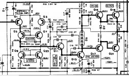
If you look at the diagram we can do a quick 'ball park' calculation on the diode current.
Voltage on either end of the chain of diodes is within a couple of volts of ground (zero volts) and the diode chain connect to the positive supply via R31 and R33 (we'll discount R35 and R45 because they are low in value in relation to the others). So that gives a current of 43V (the supply) divided by 6000 (R31 + R33) which is around 7 milliamps. The base of Q15 will take only a few hundred microamps and so can be discounted as well.
Adding bias adjustment should be fairly easy. Firstly you have a bit of tweakabilty with R35 and R45. There are two in parallel purely to get the correct bias.
So increasing the combined resistance will increase the volt drop and increase the bias. There are probably limits how far you could take this but I would say anything up to say 150 ohm would be fine. If you try this then use the variac because relatively small changes will alter the current a bit more than you might think. You could replace them with a preset and tweak the bias more accurately and then replace the preset with a suitable fixed value.
You could also add a 'proper' Vbe multiplier. The economy version is simply one NPN transistor of physically suitable type to mount so it contacts the heatsink and one preset.
Measuring the DC voltage across those 0.47 ohm emitter resistors will allow you to see if any bias current is actually flowing. In practice anything over a couple of milliamps will pretty much remove all distortion. So something around 1 millivolt (as low as that) is getting you 90% of the way there.
If you look at the diagram we can do a quick 'ball park' calculation on the diode current.
Voltage on either end of the chain of diodes is within a couple of volts of ground (zero volts) and the diode chain connect to the positive supply via R31 and R33 (we'll discount R35 and R45 because they are low in value in relation to the others). So that gives a current of 43V (the supply) divided by 6000 (R31 + R33) which is around 7 milliamps. The base of Q15 will take only a few hundred microamps and so can be discounted as well.
Adding bias adjustment should be fairly easy. Firstly you have a bit of tweakabilty with R35 and R45. There are two in parallel purely to get the correct bias.
So increasing the combined resistance will increase the volt drop and increase the bias. There are probably limits how far you could take this but I would say anything up to say 150 ohm would be fine. If you try this then use the variac because relatively small changes will alter the current a bit more than you might think. You could replace them with a preset and tweak the bias more accurately and then replace the preset with a suitable fixed value.
You could also add a 'proper' Vbe multiplier. The economy version is simply one NPN transistor of physically suitable type to mount so it contacts the heatsink and one preset.
- Status
- Not open for further replies.
- Home
- Amplifiers
- Solid State
- Kenwood KA-405 - smoke problem!