Hi Folks,
here is Kenwood KA-4006, made circa 1972-1974. Many enthusiasts love this amplifier for warm sound, marvelous exterior and exceptional quality of chassis. I acquired it from eBay a couple years ago. The amplifier was refurbished and re-caped, preserving as many of original components as (reasonably) possible.

Lately I’ve made a major upgrade. I’ve applied Burson Supreme Sound OpAmps V4, what I’d got from Parts ConneXion, to replace two original JRC4558 opamps with round body. One was on the tone/preamp board, operating at +/- 9V and the second in the phono section, operating at +/- 13V.

original JRC4558 opamp
The magic of Burson opamps is in the discrete design philosophy. You may learn more, download datasheets directly from Burson Audio. https://www.bursonaudio.com

Burson Supreme Sound OpAmp V4
First try was an epic fail. I replaced opamps and obtained a total silence. No signal at all. It was my fault, I hadn’t read the V4 datasheet. Dual Burson Supreme Sound OpAmps V4 are rather greedy for power – the quiescent current is 40 mA for each VDC and VCC supply inputs. For comparison: JRC4558 supply current is only 2.3mA (typ). So I overlooked that original +/- 14V supply stage was a simple parametric stabilizer consisting of two resistors and two zeners – R1, R2, ZD1, ZD2. It was too feeble to provide needed current. Due to lack of time I temporary putted two Burr-Brown OPA2134 to keep amplifier operative and paused the project for a long time.

KA-4006 power supply board
Now I added a separate stabilized power supply circuitry for Burson OpAmps and the machine runs “from the first kick”🙂. For time saving reason I added pre-ready stabilizer kit with LM317 LM337. It’s rather good in operation, has a high-quality PCB. The new +/- 14V stabilizer was mounted through bronze 20 mm stand-offs over the original PS board. In the future I plan to replace it with a self-made stabilized PS with bipolar transistors.

Power coupling caps are now BlackGate shunted with 0.1uf foil capacitors. Current limiting resistors were decreased in value, Ri27 and Ri28 on the Tone Amp Board – from 680 Ohms to 110 Ohms. Rd19 and Rd20 on the Phono Pre amp board – from 220 Ohms to 24 Ohms.

power coupling BlackGate's
I should mention that FET’s in Burson OpAmps are warm, and those in the phono section with higher supply voltage (+/-13V) are even warmer. But I think it’s normal since the maximum supply voltage per datasheet is 20V.


new discrete opamp comfortably sitting between "two floors" of PCB


second V4 on the phono preamp board
Listening experience: you should consider that Burson OpAmps need at least 100 hours to burn in. Every hour during that period of time they “blossom out” more and more and start to “breathe”. The discrete audio opamps are a significant step up from general use, giving a more detailed, and refined sound with a much improved sound stage. Sound gets more smooth, flowing and relaxed, revealing new micro details. Bass is smoother but punchy and more outlined. Vocals are more vivid but still warm and natural.

here is Kenwood KA-4006, made circa 1972-1974. Many enthusiasts love this amplifier for warm sound, marvelous exterior and exceptional quality of chassis. I acquired it from eBay a couple years ago. The amplifier was refurbished and re-caped, preserving as many of original components as (reasonably) possible.
Lately I’ve made a major upgrade. I’ve applied Burson Supreme Sound OpAmps V4, what I’d got from Parts ConneXion, to replace two original JRC4558 opamps with round body. One was on the tone/preamp board, operating at +/- 9V and the second in the phono section, operating at +/- 13V.
original JRC4558 opamp
The magic of Burson opamps is in the discrete design philosophy. You may learn more, download datasheets directly from Burson Audio. https://www.bursonaudio.com
Burson Supreme Sound OpAmp V4
First try was an epic fail. I replaced opamps and obtained a total silence. No signal at all. It was my fault, I hadn’t read the V4 datasheet. Dual Burson Supreme Sound OpAmps V4 are rather greedy for power – the quiescent current is 40 mA for each VDC and VCC supply inputs. For comparison: JRC4558 supply current is only 2.3mA (typ). So I overlooked that original +/- 14V supply stage was a simple parametric stabilizer consisting of two resistors and two zeners – R1, R2, ZD1, ZD2. It was too feeble to provide needed current. Due to lack of time I temporary putted two Burr-Brown OPA2134 to keep amplifier operative and paused the project for a long time.
KA-4006 power supply board
Now I added a separate stabilized power supply circuitry for Burson OpAmps and the machine runs “from the first kick”🙂. For time saving reason I added pre-ready stabilizer kit with LM317 LM337. It’s rather good in operation, has a high-quality PCB. The new +/- 14V stabilizer was mounted through bronze 20 mm stand-offs over the original PS board. In the future I plan to replace it with a self-made stabilized PS with bipolar transistors.
Power coupling caps are now BlackGate shunted with 0.1uf foil capacitors. Current limiting resistors were decreased in value, Ri27 and Ri28 on the Tone Amp Board – from 680 Ohms to 110 Ohms. Rd19 and Rd20 on the Phono Pre amp board – from 220 Ohms to 24 Ohms.
power coupling BlackGate's
I should mention that FET’s in Burson OpAmps are warm, and those in the phono section with higher supply voltage (+/-13V) are even warmer. But I think it’s normal since the maximum supply voltage per datasheet is 20V.
new discrete opamp comfortably sitting between "two floors" of PCB
second V4 on the phono preamp board
Listening experience: you should consider that Burson OpAmps need at least 100 hours to burn in. Every hour during that period of time they “blossom out” more and more and start to “breathe”. The discrete audio opamps are a significant step up from general use, giving a more detailed, and refined sound with a much improved sound stage. Sound gets more smooth, flowing and relaxed, revealing new micro details. Bass is smoother but punchy and more outlined. Vocals are more vivid but still warm and natural.

Hi, Mike!
Good job on making your amplifier upgrade project and describing the details. Well done, indeed! I like your pictures and meticulous approach to the process.
I've noticed the old-school wiring (from Burson to mainboard) with solid core wires, wrapped in cotton. IMHO, It's overhead for only solid-state upgrade 😉, but nevertheless this causes a great respect for yours knowledges and thoroughness.
Those supplies (+/- 9v, +/- 13v) sure don't allow for any headroom, do they? That 6 db of deficiency surely must be audible.
I'm not sure you are right. Those supplies are original and determined by Kenwood research engineers (who were clever enough I presume). Absolutely nothing limited them to feed opamps with +/-14V, nevertheless they had chosen +/-9V for tone circuit and +/-13V for phono preamp. Besides, tone circuit is in fact a line preamp with gain about 1 and dealing with a small signal 200-500mV. So there is a plenty of headroom relatively to supply voltage.
And what headroom are you talking about?
Thank you.
And what headroom are you talking about?
Thank you.
This might be fun to try - an all FET discrete opamp using SMT's on a tiny PCB:
http://www.diyaudio.com/forums/pass-labs/120445-pass-discrete-opamp-dip-8-package.html
http://www.diyaudio.com/forums/pass-labs/120445-pass-discrete-opamp-dip-8-package.html
Well, personally I like to keep my line-level circuits all operating at ~1 volt RMS nominal in order to ride as high above the noise floor as possible (trying to achieve a minimum of 80 db S/N ratio for all sources, including phono). That requires +/- 17 rails to achieve 24 db of headroom; clipping is the worst of all evils in solid-state amplifiers.I'm not sure you are right. Those supplies are original and determined by Kenwood research engineers (who were clever enough I presume). Absolutely nothing limited them to feed opamps with +/-14V, nevertheless they had chosen +/-9V for tone circuit and +/-13V for phono preamp. Besides, tone circuit is in fact a line preamp with gain about 1 and dealing with a small signal 200-500mV. So there is a plenty of headroom relatively to supply voltage.
And what headroom are you talking about?
Thank you.
dotneck, thank you for comment.
On the whole I share your point, it’s always better to have a higher signal in line-level circuits to be much higher above the noise floor, whereas we in no way can allow clipping.
But in this particular project the opamp buffer directly adopts output signals from various sources. It may be CD, DAC, phono stage, tape deck, DVD player etc. and they may have various output levels, from −10 dBV in consumer audio (about 300mV RMS) to +4 dBu in professional audio (1.228V RMS).
In case of an opamp buffer its output signal voltage is limited only with the total supply voltage (+ and -). In my case it is 18V what means 25.1 dBV or 27.3 dBu and that’s the headroom relative to 1V RMS = 0 dBV. Even considering microshort peak spikes in musical signal it is more than enough.
We should remember that dBV is a common use for consumer gear (unbalanced), whereas dBu is used for studio gear (normally balanced). The level difference between dBV level and dBu level is 2.2 dB. As a common standard the maximum undistorted line level of audio gear might be +18 dBu in Europe and +24 dBu in USA.
+/- 17 rails give us 34V sweep or 30.6 dBV or 32.85dBu.
Correct me if I'm wrong but it’s not clear to me why you determined that 80 dB S/N ratio just needs +/- 17V and why it gives 24 db of headroom (?). Moreover, earlier you told about some 6 dB of deficiency… Where? How do all those values correlate to each other?
My guess is you’ve got 24 dB value taking into consideration only one 17V rail i.e. the half of a total supply. That’s not correct I presume.
Last edited:
Your math is a bit off---18 volts peak relative to 0dbv (1 volt RMS) is indeed 25.1 db, but relative to 0dbu (1.23 volts RMS, 1 mwatt into 600 ohms), it is 23.3 db.On the whole I share your point, it’s always better to have a higher signal in line-level circuits to be much higher above the noise floor, whereas we in no way can allow clipping. In case of an opamp buffer its output signal voltage is limited only with the total supply voltage (+ and -). In my case it is 18V what means 25.1 dBV or 27.3 dBu and that’s the headroom relative to 1V RMS = 0 dBV. Even considering microshort peak spikes in musical signal it is more than enough. We should remember that dBV is a common use for consumer gear (unbalanced), whereas dBu is used for studio gear (normally balanced). The level difference between dBV level and dBu level is 2.2 dB. As a common standard the maximum undistorted line level of audio gear might be +18 dBu in Europe and +24 dBu in USA. +/- 17 rails give us 34V sweep or 30.6 dBV or 32.85dBu. Correct me if I'm wrong but it’s not clear to me why you determined that 80 dB S/N ratio just needs +/- 17V and why it gives 24 db of headroom (?). My guess is you’ve got 24 dB value taking into consideration only one 17V rail i.e. the half of a total supply. That’s not correct I presume.
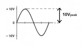
But, in any case, you are confusing peak-to-peak voltage with peak voltage. Audio has to swing both ways, so to speak. You must also allow for the dropout voltage of the amplifier. +/- 9 volt rails will allow for a peak voltage swing of ~ 7.5 volts in most op amps (No specification for this provided by Burson). This will give +17.5 db of peak headroom over a 1 volt signal. Even a rail-to-rail opamp (OPA1612 bipolar or OPA1642 FET) will only swing to within about a half volt of the supply voltage, giving an additional 1 db of headroom. In my case (with LM4562 op amps), they will swing to within 1 volt of the rail (maximum 17 volts); hence 16 volts peak= +24 db of headroom.
The signal-to-noise ratio is only relative to supply rails if you consider it a must to have 24 db of headroom above the nominal value (which I do). My LM4562-equipped phono preamp puts out 1 volt RMS from the nominal 3.5 mv at 1.35K source impedance of my Shure V-15 cartridge (~49db of gain). This leaves me with noise at ~ -77 dbv. Not quite 80, but close.
OK, let's put aside dropout voltage of the amplifier (I agree it's present), let's put aside a little mess with dBu. And I'm not confusing peak-to-peak voltage with peak voltage. As you've correctly mentioned above audio has to swing both ways. That's why I don't understand why do you keep talking about a peak voltage swing? Do you like listening only half-waves? No. You are listening full waves, positive half-wave and negative one. In other words you are listening to peak-to-peak voltage signal.
Attachments
OK, let's put aside dropout voltage of the amplifier (I agree it's present), let's put aside a little mess with dBu. And I'm not confusing peak-to-peak voltage with peak voltage. As you've correctly mentioned above audio has to swing both ways. That's why I don't understand why do you keep talking about a peak voltage swing? Do you like listening only half-waves? No. You are listening full waves, positive half-wave and negative one. In other words you are listening to peak-to-peak voltage signal.
Of course we are listening to peak-to-peak waveforms. It's just assumed that the negative portion of the waveform is supplied by the negative portion of the supply. A 16 volt peak signal in audio requires a +/- 17 volt supply---16 volts for the peak and 1 volt for the dropout---both on the positive and negative sides. Your +/-9 volt supply will swing to +/- 9 volts minus the dropout voltage. Assuming 1 volt of dropout, this leaves 8 volts, or +18db of headroom over 1 volt RMS. Or, + AND - 18 db, if that's the way you want to see it. That's insufficient. 6 db insufficient.
dotneck335, I should apologize to you. It was a kind of “brain eclipse”. Nobody is proof against that. You are right concerning output level relative to +/- supply voltage. In the light of this it still remains a mystery why Japanese engineers decided to lower supply from +/-14V to +/-9V in this circuitry. On the other hand the line input sensitivity for this amplifier (per service manual) is 150mV, ie -16.48dB.
No problem; I've had a few brain farts of my own! I still think you ought to make the most of those Bursons and turn your 317/337 supply up to at least +/-17 volts.
This might be fun to try - an all FET discrete opamp using SMT's on a tiny PCB:
http://www.diyaudio.com/forums/pass-labs/120445-pass-discrete-opamp-dip-8-package.html
xrk971,
thank you for an interesting link.
I believe it’s the right way to get rid of any IC’s in the audio signal path. An IC op-amp is entirely constructed on a single slice of silicon wafer smaller than a grain of rice. Limited by size and heat dispersion it’s impossible to incorporate top quality audio components. Regular IC op-amps are designed to be as versatile as possible. To achieve that the densely-packed circuits inside an op-amp have too much micro transistors and other micro-components that are chemically formed and inferior in every way to discrete components. Many of built-in components and corrective networks in IC’s aren’t even used for audio amplification further spoiling the signal. The conductive layer in commercial op-amps is formed with a layer of aluminum-vapor that’s thinner than the water vapor left on a foggy windshield. The close proximity of components creates electromagnetic interference or EMI that further dirties the audio signal. Furthermore, all components in the commercial op-amp’s silicone are formed by droplets of chemicals like an inkjet printer. This process just can’t create parts like precise low%-tolerance resistors, or the super-stable capacitors. Since they’re all integrated, they can’t be individually tested and matched.
What sound could you get if try to build an audio circuitry using cheapest components with a dispersion of parameters and connecting them with an aluminum or steel wire?
So, how much does Burson pay you to write such complete and utterly false propaganda?
Nobody paid. Moreover, I have no connection with any of op-amp manufacturers, whether it be Sparko's, Burson or DEXA or anything else. Just bought one day a couple of descrete op-amps and made a little upgrade project. That's it.
And if without insults - what is wrong? Do you mean IC's are better for sound than high quality discrete components? Correct me please if I'm wrong.
And if without insults - what is wrong? Do you mean IC's are better for sound than high quality discrete components? Correct me please if I'm wrong.
"op-amp have too much micro transistors"
What does that mean? Why are discrete transistors different?
"micro-components that are chemically formed and inferior in every way"
Can you explain how and why this doesn't show up in measurements.
"formed with a layer of aluminum-vapor that’s thinner than the water vapor left on a foggy windshield"
Why is this relevant at all?
"The close proximity of components creates electromagnetic interference or EMI that further dirties the audio signal."
Why can this distortion not be measured?
"What sound could you get if try to build an audio circuitry using cheapest components with a dispersion of parameters and connecting them with an aluminum or steel wire?"
A logical leap that makes no sense.
Why are ICs good enough for medical imaging other test equipment that place much higher demands on the amplifier, but magically not good enough for audio?
So yes, you are very confused and wrong.
Really? So why then primitive tube amps do sound best whereas there's a plenty of amazing mega-complex microchips?
On the whole this leads us away to another "holy war" between "electricians" and audio DIY-ers. Of course everyone has a right to be under own delusion but here it might be off-topic.
If there are questions about technical details of upgrade I'll be glad to answer, discuss or learn something new and useful.
Thank you for comment.
Last edited:
- Status
- Not open for further replies.
- Home
- Amplifiers
- Solid State
- Kenwood KA-4006 upgraded with Burson V4 Opamp