Hi guys
I need help with this beautiful Kenwood CD player.
The drawer opens and closes, display is OK, but the motor that moves the lens does not powered (no voltage to it - CN5)
There is no mechanical obstacle to movement along the axis, but no matter where I put it it doesn't go back to the beginning to read TOC
Power to driver Q19 - STA341M is OK (+-10V)
Any ideas how to proceed?
Thanks and happy holidays!
Attachments
Hi. Try to check end position limit switch , who closes contacts when tray reaches toc position. If you poweroff cd player and manually move laser to some not initial position , then turn on power , laser don't get moved too ? Check voltages of driver input.
Hi. Switch is OK.
The laser never moves, the lens too, the disc motor too.
Driver input voltages is OK, The driver itself STA341M has been desoldered and tested. All transistors are OK
The laser never moves, the lens too, the disc motor too.
Driver input voltages is OK, The driver itself STA341M has been desoldered and tested. All transistors are OK
Looks like drawer closing operation didn't finish, at least mcu thinks so . Need to check all the signals to mcu pins ,if they are changing if you open close drawer , there should be limit switches too.
Very hard to diagnose at a distance.
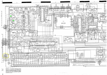
Is the supply to IC1 correct (pin 15) and can you see any change in voltage on pin 13 of IC1 during times when the sled motor should operate?
Is the supply to IC1 correct (pin 15) and can you see any change in voltage on pin 13 of IC1 during times when the sled motor should operate?
Drawer closing switch is OK.
Supply voltage to IC1 e stable 5V (measured with a multimeter). On pin 13 no voltage appears.
Supply voltage to IC1 e stable 5V (measured with a multimeter). On pin 13 no voltage appears.
Ic1 pin27( servo ic) does provide voltage to lens tracking signal driver , which also used later to control motor , which moves laser to toc position.
Supply voltage to IC1 e stable 5V (measured with a multimeter). On pin 13 no voltage appears.
It was worth checking. This is difficult at a distance.
I wonder if there is more going on internally in IC1 than the basic symbols imply. The sled motor normally shuffles along when the tracking voltage (to the tracking coils) exceeds a given voltage, however to move the sled quickly the tracking itself should be partially disabled and I can't see how that is done.
Most faults like this have a simple cause... usually mechanical like switches and so on... but that is not always the case 🙁 You have to go around the IC and check what you can. Look at every pin. Use a scope to see if the data and clock inputs are present and at the correct (5v) levels. Only when you are sure nothing looks amiss does a chip have to be proved by substitution... and I always say 'its never the big chip' but just occasionally it is.
Also , you said focus lens don't move up and down, so i think laser is turned off too . Have you checked -5v negative supply voltage ? Also from picture you posted , some signals like FE are coming from another board on the left side . Worth checking connectors . Looks like some part of servo isn't functional. Tray open close is controller by microcontroller, have you checked signals ? At which ic1 pin appears voltage, when tray opens ,at which when closes , and so on.


Pictures show no data communication , i see no clock in example. But by looking at schematic , why tray loadind works , can be explained simply - there are two signals , generated by mcu. Look at it pins 35 36, there are signals open and close . All what is not working is servo functions. Either communication lines are dead/shorted/bad ic , maybe pullup resistor open. Try to repeat measurements with scope on all communication pins from mcu side ,in respect to gnd , from moment when you start open tray ,insert disk ,close tray. Communication should appear , when tray finished loading disk , and servo ic should be instructed by mcu to search for focus and turn on laser power. Maybe there are other ics , hanging on the same data lines and having no proper supply voltage, thus preventing communication. Also i don't see laser amplifier ic on this part of schematic .
I would have expected some clock signal to be present, in fact I would have thought that should be present all the time. Looks to be derived from IC 3 pin 27. Given that the tray operates normally suggests IC3 actually working OK, or at least partly so.
Some good news guys.
I found a bad resistor and capacitor in the signal processor power supply. I replaced the bad ones, but I got the usual problem - the disc is not recognized.
The lens moves to the center of the disc, moves up/down, the disc spins briefly, then shows "Disc out".
I cleaned the lens but to no avail ;//
Probably the laser lost its power , needs replacement. As test temporarily try to increase laser current ,but very careful, it's shortens laser life ( if there's any left ). Or there's dust inside laser , maybe at prism , need to clean that then and restore laser power potentiometer position . Mark position before adjusting !
Well done 👍 Any idea why the cap and resistor effected the sled motor and so on?I found a bad resistor and capacitor in the signal processor power supply.
Has this player got some hidden history? Could it have been twiddled in the past perhaps? Once you find a definite fault it should often work once that is corrected.
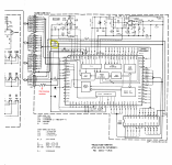
It looks like the laser might use a negative rail (going off the terms used such as LDG and LPD). Worth investigating. I would expect a 5 volt supply for laser. If LDG means laser diode ground then the supply (LDP) must be negative.
Its not easy to follow as a pdf that is split across lots of pages.
Oh , discrete laser power regulator... First check all these electrolytic capacitors for capacity loss or increased esr ,or just replace them.
The volt drop across R1 will give a good indication as to the state of laser. Typically you might see 50 to 60 milliamps which would be a drop of 0.5 to 0.6 volts across that resistor. If you try that then I would tag wires to the resistor and connect it securely to the DVM first. One short or slip to the wrong point and the laser is gone.
The signal and voltage that was missing on IC1 pins 7-10 must come from this chip (also IC1, but on the vertical board)Any idea why the cap and resistor effected the sled motor and so on?
By the way, the resistor, which was overloaded and burnt due to a shorted electrolytic capacitor missing from the schematics.
The player is in very good condition, inside is very clean, there have been no previous interventions on it.
The fight continues 🙂
Attachments
Ah, interesting. I assume a pretty low value R for that one. No excess drop across it?
Faults like that are so definite that it should all work once that is corrected.
Faults like that are so definite that it should all work once that is corrected.
- Home
- Source & Line
- Digital Source
- Kenwood DP-1100D need attention