The tweeter doesn't sound, but it works if I connect it directly bypassing the crossover. So could this fluffy resistor/capacitor be the problem?
Can I just replace that component if so where can I buy one? Falcon acoustics are out of kits...
Can I just replace that component if so where can I buy one? Falcon acoustics are out of kits...
Attachments
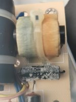
Use a DMM and measure across the leads and see if you get 10ohms or whatever the rating is. The fuzz looks like some sort of salt based crystal - more likely the stuff that evaporated out of the non polar electrolytic caps nearby. I suspect you may have some bad caps that need replacing. Those caps look like film caps which form go bad but why do they say “NP” and have such low voltage ratings?
No idea its how I bought them..
They sounded lovely last time they were working. Had them stored for a few weeks.
They sounded lovely last time they were working. Had them stored for a few weeks.
Hi do you know a good source? I'm really new to this so values/recommendations/ component values on where to buy, what to buy would be great. I'm in Ireland. I noticed Falcon acoustics are sold out...
I can solder.
I can solder.
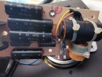
Those caps are electrolytic. If you need/want to replace them, use same type, and not film ones.
I can't see the markings on the fluffy item, but probably it is a resistor, which isn't supposed to go bad. Can you remove the deposit and retake a picture?
Anyway, before replace anything, I'd search the problem. You can simply have a bad solder joint, moving the speakers broke a contact. If you have access to a multimeter (even a very cheap one is sufficient), measure the values of the components, and more importantly measure the contact between every couple of adjacent components (you should measure 0 or near zero Ohm). Check also the wires. If you can't measure, try first to resolder everything in the tweeter path.
Ralf
Thanks, Ralph bit biusy will upload photo when I get a moment - I have a multimeter. When you say measure between adjacent components - does it matter which end of the component you place the prods/needles/whatever they're called?
Replace the lot with Alcap from Falcon (assuming they are out of spec) - Alcap 50V Standard Electrolytic capacitors for all audio and hi-fi loudspeaker crossover applications.
Don't replace with polypropylene because the ESR is different. You could ring Falcon first to see what they suggest. I see they do capacitor kits but I don't see yours mentioned.
Don't replace with polypropylene because the ESR is different. You could ring Falcon first to see what they suggest. I see they do capacitor kits but I don't see yours mentioned.
A good joint, soldered or not, should measure zero Ohm. The first thing you should do is measure the resistance of the probes, so you can subtract this value from the other measurements. Connect the two probes and read the resistance: in my multimeter this value is 0.6 Ohm, so I know that when measuring a 1 Ohm resistor I should expect to measure 1.6 Ohm instead.When you say measure between adjacent components - does it matter which end of the component you place the prods/needles/whatever they're called?
As to what measure, let me make an easy example. Imagine your crossover consist of a resistor followed by a cap, so you have a wire that goes from the speaker + terminal to the PCB, then there is the resistor, then the cap, then another wire that goes to the tweeter + terminal, then finally another wire that goes from the tweeter - terminal to the speaker - terminal.
So put a probe (doesn't matter which one), on the speaker + terminal and the other probe on the lead of the resistor near the body (*) (the lead that goes to the speaker terminal). This way you are checking at one time the connection between the speaker terminal to the wire, and the two solder joints between the wire and the resistor. This measure can be some few tenths of a Ohm depending on the wire length and diameter, but should be less than 0.5 Ohm.
Next put a probe on the other lead of the resistor and the other probe on the lead of the cap that connect to the resistor. This should measure really zero, as you are checking two solder joints and a short PCB trace.
Then put a probe on the other lead of the cap and a probe on the tweeter + terminal. This measure can be again not zero depending on the wire but definitely less than 0.5 Ohm.
Last measure is between the tweeter - terminal and the speaker - terminal.
(*) When a component is soldered to a PCB, I usually put the probe on the part that don't have the traces, to be sure to include in the measure also the connection between the component and the trace (the solder joint).
Hope this makes some sense.
Ralf
- Home
- Loudspeakers
- Multi-Way
- Kef 104AB crossover fluff