Hi Guys
I wish to use this old car stereo mainly for its amplifier.
I have seen many "hacks" on you tube soldering directly in to the main board. Not keen.
Reviewing many threads in car audio made me realise the 8 pin Din connector was likely to give a CD player access (I originally presumed it was an output to an external amp).
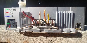
From another thread's circuit diagram (a GM 120 - thank you) I have considered the pin assignments. i.e. 2 = GRND 3 = R in 4 = L in. See my photo. Correct me if I am wrong.
So, to use these inputs for an AUX connection, I can wire up a 8 pin Din and hey presto! Right?
Hmmm … I don't think its going to be that simple.
I imagine I need to do something with the other pins.
Can anyone comment and point me in the right direction?
Appreciate it
Cheers
Fud
I wish to use this old car stereo mainly for its amplifier.
I have seen many "hacks" on you tube soldering directly in to the main board. Not keen.
Reviewing many threads in car audio made me realise the 8 pin Din connector was likely to give a CD player access (I originally presumed it was an output to an external amp).
From another thread's circuit diagram (a GM 120 - thank you) I have considered the pin assignments. i.e. 2 = GRND 3 = R in 4 = L in. See my photo. Correct me if I am wrong.
So, to use these inputs for an AUX connection, I can wire up a 8 pin Din and hey presto! Right?
Hmmm … I don't think its going to be that simple.
I imagine I need to do something with the other pins.
Can anyone comment and point me in the right direction?
Appreciate it
Cheers
Fud
Attachments
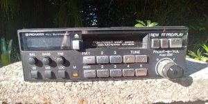
This head unit has very low power output. It's likely about 5 watts/channel.
That connector was likely used to insert an EQ if the pins in jumper are connected. If the circuit is before the volume control, it may work.
How would you switch from CD and radio?
That connector was likely used to insert an EQ if the pins in jumper are connected. If the circuit is before the volume control, it may work.
How would you switch from CD and radio?
Thank Perry,
Yes this is an old unit, I cant remember which of my first cars it came out of.
I was thinking 10w/ch but 5w is more likely.
"pins in jumper"? Now you have exposed my basic knowledge of electronics and diy audio. So this connector may not have been for a CD player?
My pin assignment is simply from another post regarding use of a 8 pin din in another Pioneer model. The input appeared to be before volume control.
I was assuming inserting a CD would have 'activated' a signal - via the din - to the head unit to switch from either cassette/radio to CD. Unlikely given your knowledge of how these early models connected CD units?
I was hoping two of the other pins might be assigned to this, and in my naivety thought a small wire from one (pin) to the other would "trick" the head unit.
This is the sort of thing I was thinking about while NZ was in a Level 4 Covid 19 isolation period: how can I use items in my garage for little projects. Always figured the unit might be useful connected to a 12 V supply (solar derived) in my garden shed! Although occasionally consider playing old cassettes, playing MP3 from my smart of course sounds better.
Kind Regards
Fud
I looked up the specs on another Pioneer that didn't have the balanced/bridged output and they spec'd it as 8 watts.
The Ke is the low power version. The KEH would have been the higher power, 20w per channel output.
The Pioneer decks that controlled the changers had a P after the hyphen. KEH-P**** or DEH-P****.
You can use the internal amp if you make a DIN that goes to a plug that will plug into your phone.
The Ke is the low power version. The KEH would have been the higher power, 20w per channel output.
The Pioneer decks that controlled the changers had a P after the hyphen. KEH-P**** or DEH-P****.
You can use the internal amp if you make a DIN that goes to a plug that will plug into your phone.
That's an OEM Honda unit, right? Look at the shorting plug to see which pins need to be connected when you want to use the radio/cassette. Pins may even be labelled on the PCB if you pull the cover off. DPDT relay or switch needed to change between aux and internal FM/cassette. I may still have a diagram somewhere from back when...
Many thanks again guys.
I will have some time in the weekend to work on this.
If a useful diagram is possible I would appreciate it.
Regards
Fud
I will have some time in the weekend to work on this.
If a useful diagram is possible I would appreciate it.
Regards
Fud
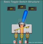
The switch below is half of what you need. This is a SPDT, you need a DPDT which will have two rows of 3 terminals. One group of three goes to one channel and the other group of three, to the other channel.
In this image, the B terminal goes back into the deck. The A terminal goes to one channel of the external source. The C terminal is the output of the DIN from one channel of the deck's internal sources.
When in the current position, the external audio would play through. When the toggle was flipped, the deck would play through as if you had the jumper plug in place.
Attachments
- Home
- General Interest
- Car Audio
- KE-5120 zh. I wish to input via the Din