Jvc k2 XL-Z1010tn a cracker cdp
I have this player and it sounds very good after I direct coupled for dac to output with AD825's for I/V's and buffers, got rid of the muting, headphones and variable outputs, de-emphasis circuit left in.
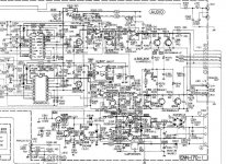
Can anyone tell me what is the Fet before the I/V stage doing it get's triggered by the pin 3 of the 2 x PCM56P K dac chips my data on the PCM56 says pin 3 is the Positive Logic Supply and that's it nothing else, I have a Wadia 64.4 with the same dac chips and there is no fet before the I/V being triggered by this pin 3 of the dac, and both Wadia and the JVC use the PCM56 in current output mode and don't use it's inbuilt i/v.
Cheers George
I have this player and it sounds very good after I direct coupled for dac to output with AD825's for I/V's and buffers, got rid of the muting, headphones and variable outputs, de-emphasis circuit left in.
Can anyone tell me what is the Fet before the I/V stage doing it get's triggered by the pin 3 of the 2 x PCM56P K dac chips my data on the PCM56 says pin 3 is the Positive Logic Supply and that's it nothing else, I have a Wadia 64.4 with the same dac chips and there is no fet before the I/V being triggered by this pin 3 of the dac, and both Wadia and the JVC use the PCM56 in current output mode and don't use it's inbuilt i/v.
Cheers George
Attachments
Last edited:
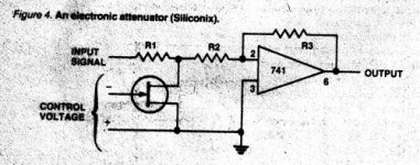
haha , this is a funny one . Once signal falls below -80dB or so, they apply gain in digital realm of 12.02 dB. Then in the analog realm, the FET acts to remove the gain. So you gain +2 bits. Because of practical reasons ( signal level rarely that low) I doubt this feature sees much use. Thanks for posting, Ill check the schem later cause its hard on the eyes.
Last edited:
haha , this is a funny one . Once signal falls below -80dB or so, they apply gain in digital realm of 12.02 dB. Then in the analog realm, the FET acts to remove the gain. So you gain +2 bits. Because of practical reasons ( signal level rarely that low) I doubt this feature sees much use. Thanks for posting, Ill check the schem later cause its hard on the eyes.
Thanks tritosine/bernhard, I thought this was weird do you think I should remove it as well? this is as clear as the service manual comes, 1989.
This is an amazing sounding unit once mods were done, it was very good standard as well.
The K2 interface board must have something to do with it also, a company Reiymo ( http://www.combak.net/reimyo/DAP-999.htm ) has got great raps on their top dac unit which has the K2 interface in it licensed from JVC, and I heard all JVC XRCD's are produced using this K2 interface thing it's starting to make a comeback, it is a very complex board next time I have it out I'll post a pic, the service manual has no info on it just a blank board that says K2 interface I think they kept it close to their chests, a couple of people have said it's just an XO clock board, but I can tell you it's far far more complex than that.
Also the next model up the XL-Z1050TN had the K2 interface but sadly JVC used their own bitstream dacs in it and it has nowhere near the dynamic swing and detail of the twin PCM56P's in the XL-Z1010TN
Cheers George
Last edited:
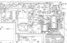
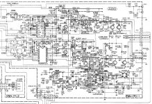
Hi tritosine, sorry about the clarity of the schematic that's as good as it gets, did you get to study the operation of the FET a bit more? how would you say it would impact on the sound? Also I managed to find a circuit of the K2 Digifine Interface board, as you can see it's a complex one.
As Bernhard said the optocoupler (IC 307) switches the FET and it get triggered by the DGL pin 11 of the (IC 918) a JVC VC4098 IC on this K2 Interface board, the only thing I could find on this VC4098 is that UED was selling them for JVC for $22usd each!!!
Cheers George
As Bernhard said the optocoupler (IC 307) switches the FET and it get triggered by the DGL pin 11 of the (IC 918) a JVC VC4098 IC on this K2 Interface board, the only thing I could find on this VC4098 is that UED was selling them for JVC for $22usd each!!!
Cheers George
Attachments
Last edited:
HI! No yet, but its an easy thing to do , its just shifting bits towards bigger amplitudes, so in soundquality perspective it must be harmless, and you gain better resolution on those lowest amplitudes. I even tought of implementing it , but according to my adventures with FFt and staring at peak amplitudes in real time , it would be very rarely triggered. Maybe its sorta work around becase they did not sort dac chips to the degree like Bernhard does (the type P-J wont give away that, because those are stamped on without trimming by hand).
BTW I read the K2 was employing some anti jitter countermeasures, and it was one of the lowest jitter players around.
BTW I read the K2 was employing some anti jitter countermeasures, and it was one of the lowest jitter players around.
Last edited:
one thing is for sure though, you can't just turn it off! The k2 chip will shift 2 bits towards MSB once the amplitude is low enough, and if theres nothing to attenuate it back in the analog realm, its like someone switched on +12 dB gain (in the most silent moments). Maybe a better switching element wouldnt hurt.
HI! No yet, but its an easy thing to do , its just shifting bits towards bigger amplitudes, so in soundquality perspective it must be harmless, and you gain better resolution on those lowest amplitudes. I even tought of implementing it , but according to my adventures with FFt and staring at peak amplitudes in real time , it would be very rarely triggered. Maybe its sorta work around becase they did not sort dac chips to the degree like Bernhard does (the type P-J wont give away that, because those are stamped on without trimming by hand).
BTW I read the K2 was employing some anti jitter countermeasures, and it was one of the lowest jitter players around.
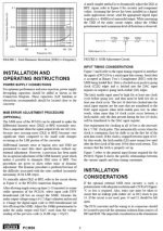
This must be why I was able to do the MSB adjustments so easily with my -80db 1khz sine wave test disc, just by using a good crow as it was so clear to see when it was out of adjustment as per the the JVC's MSB adjustment instruction (attached) except I used it's own headphone amp insted of making up one, most other I have done are so buried in the noise floor you cannot even make that it's a sine wave let alone do the MSB adjustment, this was as clear as if it was a -20db sine wave. Yes and I did read I think it was a stereophile measurment that it measured an incredable 56ppm jitter measurment, when 250ppm was considered to be very good.
Attachments

Last edited:
This is not the MSB adjust as per PCM56, but for the exact value of the attenuation to compensate the gain shift on the digital side.
This is not the MSB adjust as per PCM56, but for the exact value of the attenuation to compensate the gain shift on the digital side.
So JVC call it an MSB adjustment in the service manual.
And (attatched) it's wired down to the same values to pins 14 15 & 1 as per the Burr Brown PCM56P data sheet suggests to do MSB adjustment, yet it's not your saying? Now I am confused!!
Cheers George
Attachments
Sorry, my mistake, when I first saw how they suggest to do the adjustment, I thought it was the attenuator.
How do they provide the exact attenuation with the FET ?
How do they provide the exact attenuation with the FET ?
Sorry, my mistake, when I first saw how they suggest to do the adjustment, I thought it was the attenuator.
How do they provide the exact attenuation with the FET ?
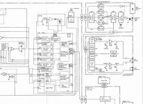
It may not be an attenuator they call the fet a "deglitcher" in this block circuit.
Cheers George
Attachments
Last edited:
Any chance of a copy of the service manual, I have a copy of the XL-Z1050TN if you are interested?
Regards
James
tvi at iinet dot net dot au
Regards
James
tvi at iinet dot net dot au
- Status
- Not open for further replies.
- Home
- Source & Line
- Digital Source
- Jvc k2 xl-z1010tn