I have already presented two slightly unusual applications of incandescent lamps:
http://www.diyaudio.com/forums/chip-amps/254384-automatic-resonance-frequency-finder.html
http://www.diyaudio.com/forums/analog-line-level/254076-one-more-volume-control.html
Here is another one: a (really working) RMS to DC converter.
It works by comparing the resistance of the lamp for two signals: the one to be measured, and an internally generated one.
A servo then attempts to minimize the difference.
When the equilibrium is reached, the amplitude of the synthetic signal accurately represents the rms value of the input.
It is a true thermal converter, meaning it can accept any peak factor or frequency without error. The only errors will be caused by the electronics around the lamp.
The technique of alternating measurements allows the use of single lamp, which is by definition matched with itself.
If one accepts the constraint of matched lamps, simpler electronics will result.
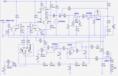
Here, the alternating signal is generated by U5 and U4 and has a frequency of 10Hz. This value is probably not optimal, it is an educated guess, but it works well enough for this proof of concept.
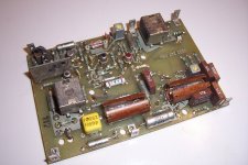
Q3 to Q6 form the alternating switch feeding the power amplifier Q1 Q2 driving the lightbulb, a 6V 40mA pilot.
Why these characteristics? It is low power and low voltage, yet robust enough, and I had it available.
It is DC-biased by R8 to measure its resistance, and the resulting 10Hz signal is extracted by U1 and synchronously demodulated by the 4053 and U2.
The resulting DC is then remodulated at ~50KHz by U3 and the other 4053.
This DC is also level-shifted by U11 to reference it to the ground and be used as the final output.
R23/C15 adapt the delay of the demodulator's reference, to compensate for the phase-shift introduced by the thermal inertia of the lamp.
The whole circuit is pretty crude and simplified, with a single supply, unmatched and non thermally-coupled input transistors, commodity IC's, yet it actually works rather well: it is usable from 150~200Hz to 10MHz (below 150Hz, the beats between the 10Hz and the input make it unusable and the upper limit results from the rudimentary amplifier), and the dynamic range extends from 40 to 450mV, one decade.
With some care, better optimization and components, two decades are probably within reach.
Note that the switch could be different: reed relays, PIN diodes, etc.
Of course, to make it into a real instrument, it would also require a proper input amplifier and step attenuator.
http://www.diyaudio.com/forums/chip-amps/254384-automatic-resonance-frequency-finder.html
http://www.diyaudio.com/forums/analog-line-level/254076-one-more-volume-control.html
Here is another one: a (really working) RMS to DC converter.
It works by comparing the resistance of the lamp for two signals: the one to be measured, and an internally generated one.
A servo then attempts to minimize the difference.
When the equilibrium is reached, the amplitude of the synthetic signal accurately represents the rms value of the input.
It is a true thermal converter, meaning it can accept any peak factor or frequency without error. The only errors will be caused by the electronics around the lamp.
The technique of alternating measurements allows the use of single lamp, which is by definition matched with itself.
If one accepts the constraint of matched lamps, simpler electronics will result.
Here, the alternating signal is generated by U5 and U4 and has a frequency of 10Hz. This value is probably not optimal, it is an educated guess, but it works well enough for this proof of concept.
Q3 to Q6 form the alternating switch feeding the power amplifier Q1 Q2 driving the lightbulb, a 6V 40mA pilot.
Why these characteristics? It is low power and low voltage, yet robust enough, and I had it available.
It is DC-biased by R8 to measure its resistance, and the resulting 10Hz signal is extracted by U1 and synchronously demodulated by the 4053 and U2.
The resulting DC is then remodulated at ~50KHz by U3 and the other 4053.
This DC is also level-shifted by U11 to reference it to the ground and be used as the final output.
R23/C15 adapt the delay of the demodulator's reference, to compensate for the phase-shift introduced by the thermal inertia of the lamp.
The whole circuit is pretty crude and simplified, with a single supply, unmatched and non thermally-coupled input transistors, commodity IC's, yet it actually works rather well: it is usable from 150~200Hz to 10MHz (below 150Hz, the beats between the 10Hz and the input make it unusable and the upper limit results from the rudimentary amplifier), and the dynamic range extends from 40 to 450mV, one decade.
With some care, better optimization and components, two decades are probably within reach.
Note that the switch could be different: reed relays, PIN diodes, etc.
Of course, to make it into a real instrument, it would also require a proper input amplifier and step attenuator.
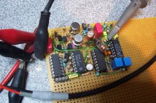
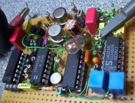
Attachments
Cool! One could also demodulate the change in lightness.
At a metrological level (where thermal converters are mostly used today), many more effects come into play; inductance, capacitance and skin effect of the lamp limit uncertainty at high frequencies. At low frequencies it's mostly the finite thermal time constant.
Samuel
The only errors will be caused by the electronics around the lamp.
At a metrological level (where thermal converters are mostly used today), many more effects come into play; inductance, capacitance and skin effect of the lamp limit uncertainty at high frequencies. At low frequencies it's mostly the finite thermal time constant.
Samuel
Indeed.Cool! One could also demodulate the change in lightness.
However, to keep acceptable performances at low levels, one would have to use a sensor other than ordinary silicon: since the low temperature thermal IR's have a longer wavelength than the Si's 850nm peak, the sensitivity would degrade very quickly.
Beyond ~1200nm, the sensitivity falls to practically zero:
At a metrological level (where thermal converters are mostly used today), many more effects come into play; inductance, capacitance and skin effect of the lamp limit uncertainty at high frequencies. At low frequencies it's mostly the finite thermal time constant.
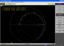
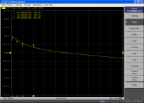
Yes, see the impedance curves below for this particular bulb:
First, the Smith chart: the equivalent inductance is ~55nH, of which 5nH is uncompensated test fixture.
Then the magnitude and phase: up to ~50MHz, the response could be corrected relatively easily. 100MHz would be reachable with some efforts.
For best HF performance, the voltage of the lamp should be as low as possible: if I had used a 1.5V/40mA bulb instead of the 6V, the inductance would have mechanically been reduced by a factor of ~4
Attachments

Just FYI--infrared sensor have been used: IEEE Xplore Abstract - Fast thin-film isothermal ac-dc converter with radiometric sensing
Samuel
Samuel
Quite a special circuit ..
In this video you see how to convert AC signal to rms .... but a very different way .. interesting too
https://www.youtube.com/watch?v=wRC_4ESuk7I
In this video you see how to convert AC signal to rms .... but a very different way .. interesting too
https://www.youtube.com/watch?v=wRC_4ESuk7I
Yes, one of the many ways to make a thermal converter.
That said, if you're adept of truly simplistic methods of measuring AC or HF currents, there is an even simpler one and it isn't thermal, yet the result should also be the rms value if my reasoning is correct...
That said, if you're adept of truly simplistic methods of measuring AC or HF currents, there is an even simpler one and it isn't thermal, yet the result should also be the rms value if my reasoning is correct...
Here is another one: a (really working) RMS to DC converter.
It works by comparing the resistance of the lamp for two signals: the one to be measured, and an internally generated one.
A servo then attempts to minimize the difference.
Neat!
Jim Williams (RIP) found the thermal converters to be the most accurate RMS measuring instruments, and for a while, Linear Tech made a thermal converter (LT1088). he wrote an application note on it: http://cds.linear.com/docs/en/application-note/an22.pdf
I have an HP3403 which uses a thermopile -- they are quite delicate, not a good item to buy if you can't test it out first.
Thanks, if you are interested in similar circuits, see also the lightbulb-based voltage reference:
http://www.diyaudio.com/forums/part...scent-light-bulbs-into-voltage-reference.html
http://www.diyaudio.com/forums/part...scent-light-bulbs-into-voltage-reference.html
The HP 3400 and 3403 electronics effectively protect the thermopyle if nothing went really wrong in the box (I have a 3403 and have had 3400's in the past) The Fluke premium meters also used a thermopyle. Possibly the 8506A being the most sophisticated with an approach pretty similar to yours and 6 1/2 digits of true RMS resolution.
Thermal converters use a heater and a thermocouple in a vacuum and are the most accurate and tedious method to do AC DC comparisons. New designs (E.g. Keysight 3458) usually use sampling techniques and software to get accurate AC measurements.
Using a lightbulb is a good trick. The resistance of the bulb changes a lot with drive. The other benefit is that they are cheap- where the vacuum thermocouple is $600 before you put it into the fixture.
For RF there is a different but related trick that simple measure the current in the RF circuit called a micropotentiometer: RF-DC Differences of Micropotentiometers . Perhaps using a light with a linear filament in a carefully crafted tube could emulate the micropot.
Nice!Thanks, if you are interested in similar circuits, see also the lightbulb-based voltage reference:
http://www.diyaudio.com/forums/part...scent-light-bulbs-into-voltage-reference.html
- Status
- Not open for further replies.
- Home
- Design & Build
- Equipment & Tools
- Just for fun: recycle your incandescent light bulbs into this RMS to DC converter