JohnAudioTech JAT501 Build Thread
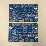
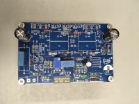
Hi, I ordered a batch of ten JohnAudioTech's JAT501 PCBs from JLCPCB. The Inline double sided version. Made from JohnAudioTech's publicly available JAT501 gerber files.
John, Thank you for your generosity and contributions to the community. Also, much thanks to the anonymous PCB designer. Much appreciated.
Attachments
Last edited:

Yes, search YouTube for JohnAudioTech and JAT501. John has a series of videos from initial design, prototypes, testing, and links to PCB gerber files on Patreon.
Good looking work, I'm looking forward to building my own amp based on these boards. Keep us posted on your progress.
Last edited:
This is the oldest video I can find that references this amp but it is already designed. Do you have a link for the design process?
John posted his JAT501 documents and gerber files on Patreon.
JohnAudioTech on Patreon
JAT501 amplifier PC board files now available! (March 9, 2022)
JohnAudioTech on Patreon
JAT501 amplifier PC board files now available! (March 9, 2022)
Last edited:
I have a 17-0-17, 100VA transformer and a small linear power supply (2 x 10,000 uF) to use for testing.


Last edited:
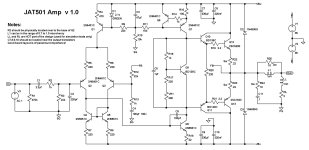
This amp is a mini (non beta enhanced) badger. It should be totally ROCK solid with that 100p miller.
NO way to go wrong with this design !
NO way to go wrong with this design !
Thanks for that confirmation @ostripper. I follow John, and while his videos are not professionally produced, he always clearly explains - in a common-man sort a way - his design approach. No flash, no pretence, just a humble guy who is passionate about the hobby and willing to share his knowledge.
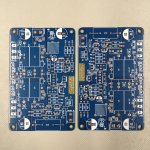
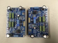
Few more components installed. In the attached photo, the bigger components are just inserted for now until all the last of the smaller ones are installed. I'm currently waiting on the last of the components to arrive. I was short four 5401's, and the BD139/140's I though I had were "-16" instead of "-10".
On making the Thiele network coils, John said in his YouTube video that he used a drill bit to form the coils but didn't say what size bit. I assumed he used 3/8" about 9.5mm?
On making the Thiele network coils, John said in his YouTube video that he used a drill bit to form the coils but didn't say what size bit. I assumed he used 3/8" about 9.5mm?
Attachments
Last edited:
Great work Sippy71
they are coming together nicely for you
a few more parts, then mounting and testing. Can't you just feel the excitement in the air!
Oh and I got your parcel today, wow those pcb's are made to a very high standard and thanks a ton for all the extra's
they are coming together nicely for you
a few more parts, then mounting and testing. Can't you just feel the excitement in the air!
Oh and I got your parcel today, wow those pcb's are made to a very high standard and thanks a ton for all the extra's
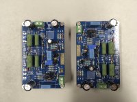
More components installed. The last of the 5401 transistors, the small ceramic caps, the 3W and 5W resistors, and the quick connect tabs are in. The rest of the components are dry fit for now. I'll make and test the coils next. Not sure if they're gong to work, but looks good so far.
Attachments

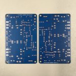
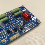
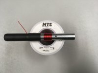
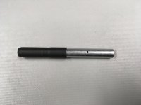
Made some progress with the coils. I formed the coils around a 10 mm bolt (M10 x 100 mm).
I cut the head off the bolt with a hacksaw, squared off the end, and removed the burrs with some sandpaper. I chucked the bolt into my drill press, and squared off the cut end using some 150 grit sandpaper double-stick taped to a block of plywood. I drilled a small hole through the middle of the bolt to hook one end of the wire. I put some thick 1/2" heatshrink around the bolt threads for extra grip.
I cut off about 60 cm of wire. Hold the newly fangled forming tool in my left hand. Hook the wire into the hole. Keep tight tension on the wire with my right hand thumb. Turn the forming tool with my left hand. The "machined" end of the forming tool rotates in my right hand palm. Put on about 16 turns as tight and gapless as possible. Cut the wire to free the coil from the hole. Take off any sloppy turns from the ends, leaving 12.5 tight turns from the middle. Now got a coil fit for purpose. I also think it needs some clear heatshrink to hold it all together.
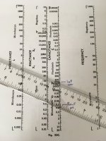
It's not tested yet, that's the next step. I need to order a new lead for my function generator. I picked up a used BK Precision 4011A Function Generator cheap off ebay. It only goes up to 5 MHz. It didn't come with any leads.
I think I can find the coil's inductance using a higher value capacitor, and a lower frequency range between 4 and 5 MHz. I have the same Radio Shack Data Book Reactance Chart John used in is coil video. See photo for a combination of 4.5 MHz, 1 nF, and about 1.2 uH.
I cut the head off the bolt with a hacksaw, squared off the end, and removed the burrs with some sandpaper. I chucked the bolt into my drill press, and squared off the cut end using some 150 grit sandpaper double-stick taped to a block of plywood. I drilled a small hole through the middle of the bolt to hook one end of the wire. I put some thick 1/2" heatshrink around the bolt threads for extra grip.
I cut off about 60 cm of wire. Hold the newly fangled forming tool in my left hand. Hook the wire into the hole. Keep tight tension on the wire with my right hand thumb. Turn the forming tool with my left hand. The "machined" end of the forming tool rotates in my right hand palm. Put on about 16 turns as tight and gapless as possible. Cut the wire to free the coil from the hole. Take off any sloppy turns from the ends, leaving 12.5 tight turns from the middle. Now got a coil fit for purpose. I also think it needs some clear heatshrink to hold it all together.
It's not tested yet, that's the next step. I need to order a new lead for my function generator. I picked up a used BK Precision 4011A Function Generator cheap off ebay. It only goes up to 5 MHz. It didn't come with any leads.
I think I can find the coil's inductance using a higher value capacitor, and a lower frequency range between 4 and 5 MHz. I have the same Radio Shack Data Book Reactance Chart John used in is coil video. See photo for a combination of 4.5 MHz, 1 nF, and about 1.2 uH.
Attachments
Last edited:
- Home
- Amplifiers
- Solid State
- JohnAudioTech JAT501 Build Thread