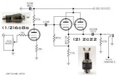
Just kidding... Well I have not completely decided on the power supply for my 6dj8 headphone amp and am waiting for some transformers for my WE407A preamp. I have nothing to do right at the moment. Joel's headphone/preamp sounded like a good combo a couple months ago so why not build it while I am waiting. I have added some minor changes to the schematic, just because of the parts I have on hand. I do have to order a 12ay7, but I think I will get a 6c8g because it will match the top caps of the 2c22 I am going to swap in for the 6sn7. Just wanted to post the changed schematics and see what Joel and others had to say. Sorry for the bucther job on your schematic Joel! I hope you will not mind.
Oh and yes I do like ASC oil caps
Oh and yes I do like ASC oil caps
Attachments
Guinness,
I liked the 6C8-G in mine. It had just the right amount of gain. Looks nice too...
I don't have my tube manual here at work, but I think you'll need to change the value of cathode resistor if you're going to use the 6C8G though. 1.8k if I remember correctly. Play around with it.
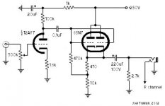
Also, there should be a resistor between the cathode followers' plates and the 6C8. You have an "old" schematic. I posted a corrected one a long time ago. Here it is again.
I liked the 6C8-G in mine. It had just the right amount of gain. Looks nice too...
I don't have my tube manual here at work, but I think you'll need to change the value of cathode resistor if you're going to use the 6C8G though. 1.8k if I remember correctly. Play around with it.
Also, there should be a resistor between the cathode followers' plates and the 6C8. You have an "old" schematic. I posted a corrected one a long time ago. Here it is again.
Attachments
Thanks Joel...
I might subsitute in a 6F8G for the 6SN7. I really like the looks of the 2c22 and have heard good things about them. I have a case of 50 of them. Need to use them up someplace. But I would need 4 sockets and 8 top caps to complete the preamp. Who knows what to do. so many tubes so little time!
Thanks again
Joel's complete preamp
Hi,question for joel.Is it possible to use half a 6n7 instead of a 12ay7 in this circuit?I'm asking as I have a few of them,all RCA nos and would like to use them in a preamp.I was thinking of using 1 6n7 followed by a pair of them paralleled.
Hi,question for joel.Is it possible to use half a 6n7 instead of a 12ay7 in this circuit?I'm asking as I have a few of them,all RCA nos and would like to use them in a preamp.I was thinking of using 1 6n7 followed by a pair of them paralleled.
Why the coupling cap?
Guys,
Just came across this thread. A common cathode gain stage followed by a cathode follower is a good simple configuration, but it shouldn't need the first coupling cap (between the two stages) and the 470K resistors to bias the cathode follower grid(s). Why not just directly connect the CF grids to the first plate? Minor resistor changes might be needed to tweak DC voltages just right, but it may not even be necessary to change them. Typically the first tube's plate sits at about 1/2 of B+ (I didn't analyse the details of this circuit that carefully) . That sets the second cathode at roughly the same voltage which is about right for the CF. Just make sure the CF's cathode resistor has enough power rating. You could add a current source there, but that get's away from the nice simplicity of the basic configuration. Getting rid of one cap can only help though.
Brian
If I understand correctly if I've got B+ of 250v for the CF and 125v on the plate of the common cathode gain stage I need 125v on the cathode of the CF.Is this correct or am I clutching at straws?
It's correct. If you want to direct couple between the tubes, it will require raising the WVDC of the output cap, floating the heaters of the 6SN7 at 150V or so, and putting a protective diode between the grid and plate of the CF to let it survive turn-on. The 470 ohm bias resistor will have to be tweaked a bit, too.
I was thinking of using a pair of OA2 regulators for the 300v B+ for the CF and a single OA2 to get 150v for the first gain stage.Will this work?
Well, the 470 ohm bias resistor will disappear altogether if you direct couple the two stages. Agree with the output cap voltage rating concern; it was too low even in the original design. I would go with a B+ or higher rating, just in case.
You can indeed get rid of the 470 ohm, along with the grid-leak. The replacement resistor will have to be sized to get the desired idle current, taking into account the necessary cathode-to-grid voltage. The nice thing is that if everything is off a bit, the circuit will still function just fine.
So if I understand this correctly:If I have 150v on the grid of the direct-coupled CF and the grid to cathode voltage is -5v@6mA do I need a resistor that drops 145v or 155v@6mA?I'm planning on using parallel 6N7G for the CF stage.
Ignore the grid to cathode voltage. The tube will take care of that itself. For the sake of approximation, assume the cathode will be a couple volts positive of the grid. Then calculate the new cathode resistor value by dividing this voltage by the desired idle current.
For example, if the grid voltage will be 150V, the cathode will be at maybe 153, 155 volts. It doesn't matter. Call it 150. If you want to run 15mA through the paralleled sections, the cathode resistor should be R = V/I = 150/15 = 10K.
As you can see, the error in ignoring (or more accurately, not knowing exactly) the cathode-to-grid voltage is pretty insignificant. If you want to be anal about it, you can use the tube curves and start laying out load lines and getting that operating point exact, but there is absolutely no advantage to doing things the hard way.
OK,thanks for all your help.I'll post a photo as soon as it's finished.One more question.Should I use a 6N7G as the first gain stage or go for a 9 pin double triode.I've got pairs of ecc81,83 and 85's in the toolbox waiting for a project.I'm going with parallel 6N7G in CF stage.
Should I use a 6N7G as the first gain stage or go for a 9 pin double triode.>
I don't like the 6N7 much, but one tube that may sound good is the 6SL7. It has several variants - 12SL7, 7F7 (loctal)
There'a also the 7F8 in loctal - mu 48
I don't like the 6N7 much, but one tube that may sound good is the 6SL7. It has several variants - 12SL7, 7F7 (loctal)
There'a also the 7F8 in loctal - mu 48
I've tried 6sl7 in my current srpp linestage and found them to have too much gain.Any suggestions apart from a 100k resistor on the input?
Oh no, don't try the 100K resistor in series with the input. Try a medium-mu triode: 5687, 6SN7, 7044, 7119, even a 12AU7A, etc.
I've tried 6sl7 in my current srpp linestage and found them to have too much gain>
I use them in diff pairs with a CCS under - that might make a difference. I guess it also depends where you put the gain - in the preamp or in the front of the amp. I prefer two stage amps, so to get the gain I tend to use 6SN7 in the pre and 6SL7 in the front of the amp, but I guess it could be the other way about.
I use them in diff pairs with a CCS under - that might make a difference. I guess it also depends where you put the gain - in the preamp or in the front of the amp. I prefer two stage amps, so to get the gain I tend to use 6SN7 in the pre and 6SL7 in the front of the amp, but I guess it could be the other way about.
SY said:It's correct. If you want to direct couple between the tubes, it will require raising the WVDC of the output cap, floating the heaters of the 6SN7 at 150V or so, and putting a protective diode between the grid and plate of the CF to let it survive turn-on. The 470 ohm bias resistor will have to be tweaked a bit, too.
I've decided on ecc85 and 6sn7 for this project.Which way round is the diode wired?
- Status
- Not open for further replies.
- Home
- Amplifiers
- Tubes / Valves
- Joel's 6sn7 Round 2...