Hi!
Impressed by the sound of the original (BJT `69 JLH amplifier) I decided to experiment a bit and this is my "enchased" version of a JLH amp.
simulation results
THD=0.002%
Power on 4 Ohm (32W)
Power on 8 Ohm (16W)
OUtput mosfets bias (2A)
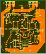
This is the PCB I made and becouse I got very little expirience in developing PCB-s, I hope you`ll hel me debug the PCB layout...
When all is done, PCB file and complete tutorial for making this amp will be attached for the interested DIY-ers.
Cheers!
Bogdan.
Impressed by the sound of the original (BJT `69 JLH amplifier) I decided to experiment a bit and this is my "enchased" version of a JLH amp.
simulation results
THD=0.002%
Power on 4 Ohm (32W)
Power on 8 Ohm (16W)
OUtput mosfets bias (2A)
This is the PCB I made and becouse I got very little expirience in developing PCB-s, I hope you`ll hel me debug the PCB layout...
When all is done, PCB file and complete tutorial for making this amp will be attached for the interested DIY-ers.
Cheers!
Bogdan.
Attachments
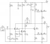

JLH Class A - IRFP240 Vertical MOSFET
.
Looks like a good nice DIY amplifier.
Using IRFP240 vertical MOSFET, HEXFET.
Push-Pull.
Single Supply.
Pure Class A.
How much bias you have across 0.22 Ohm resistors?
If simulations data are somewhat right
then you have a real good HiFi amp there!
😎
.
Looks like a good nice DIY amplifier.
Using IRFP240 vertical MOSFET, HEXFET.
Push-Pull.
Single Supply.
Pure Class A.
How much bias you have across 0.22 Ohm resistors?
If simulations data are somewhat right
then you have a real good HiFi amp there!
😎
bias is set to 2A.
the amp is wired now (point to point) and the sound is very, very good!
I just need advide on PCB. Is there some "big" errors? I have no much expirience...
the amp is wired now (point to point) and the sound is very, very good!
I just need advide on PCB. Is there some "big" errors? I have no much expirience...
- Status
- Not open for further replies.