Hello Everyone,
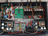
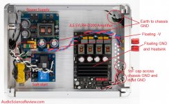
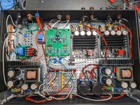
I just completed my dual mono amp using JLE Sylph-D400M TPA3255 boards, Connex Electronic SMPS600RS running at 50v, and a BTSB to convert from single ended into balanced as well as a bit of extra gain if necessary. Apologies in advance for any poor terminology, as well as the fairly messy interior, I'm still learning.
For the most part things seem to be working, however I am struggling with resolving an odd hum / noise issue that I can't pinpoint.
When the amp is on a test bench, cover off, and nothing connected to the input, there is a very faint hum if you press your ear to the speaker. When moving your finger or object near the input wire the hum increases in volume. Moving the amp over to my stand where it will live long term, I have the very faint hum, that seems to increase slightly in noise when an audio signal passes into the amp, as well as the input seems to be picking up something that I can only describe as a periodic rustling or crackling of sorts, something you only notice when close to the speaker but a problem no less.
I've removed the RCA jacks from the chassis and left them free floating with no changes to behavior. Removing the cable shield from the main ground loop breaker seems to increase volume of the hum sound.
I feel as if I have a ground loop or I am missing something else completely in my wiring and I am at my wits end trying to pinpoint it. I've attached a picture of the amp, but I am happy to take more pictures and draw functional diagrams as needed.
I would be so very appreciative if someone could help me resolve this, I know the JLE boards and the BTSB are capable of being silent and I am fairly certain I am just doing something incorrectly.
Attachments
D
Deleted member 148505
Please try the following:
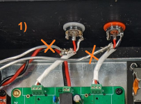
1) Make all input ground floating and connect 1nF on each input ground to chassis ground, just like on this post.
JLE TPA3255 Build and Modifications
2) Use shielded cable for the inputs.
3) GND of power supply output going to Sylph-D modules should be floating. There should be a dedicated chassis ground connection on connex SMPS.
4) Modules in close proximity should have synchronized oscillations. Configure the other module as a slave and connect their OSC_IOP and OSC_IOM together. More info in this document: SLAA787
https://www.ti.com/lit/an/slaa787/slaa787.pdf?ts=1638794260018&ref_url=https%3A%2F%2Fwww.ti.com%2F
Attachments

Please try the following:
1) Make all input ground floating and connect 1nF on each input ground to chassis ground, just like on this post.
JLE TPA3255 Build and Modifications
2) Use shielded cable for the inputs.
3) GND of power supply output going to Sylph-D modules should be floating. There should be a dedicated chassis ground connection on connex SMPS.
4) Modules in close proximity should have synchronized oscillations. Configure the other module as a slave and connect their OSC_IOP and OSC_IOM together. More info in this document: SLAA787
https://www.ti.com/lit/an/slaa787/slaa787.pdf?ts=1638794260018&ref_url=https%3A%2F%2Fwww.ti.com%2F
Thanks for the input. I must say I am a pretty embarrassed, I have two receivers, 1 upstairs, 1 downstairs. About 1 month ago my receiver downstairs worked fine with an amp, but for reasons we don't need to get into now, I did not have an amp connected for a few weeks. Last time one was connected, it worked great, why on earth would I suspect my downstairs receiver as a problem. The TPA3255 would be living downstairs and as I have two receivers with amps, I started swapping amps around between receivers, it turns out my downstairs receiver is going bad. I tried multiple amps, every interconnect I could find, all amps and all interconnects exhibited the same problem. No combination of amps and interconnects had the issue on my receiver upstairs. Now that I have my dual mono JLE Sylph hooked up to a known good receiver, it's working fantastically! Needless to say I ordered a new receiver to replace the one that is misbehaving.
Never-the-less I will still be taking in your suggestions but have some questions in those regards. If I cram my ears right onto the speaker drivers I can hear a very very faint hum, faint enough where I might be imagining it, and I am always keen to further refine my project. Please bear with me as I'm still getting the hang of all the DIY audio, so they may be bone-head questions.
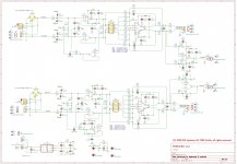
1a) The BTSB has a 100nF cap and 10ohm resistor between the ground and mounting pad to act as a loop breaker (screenshot of schematic attached), is that effectively the same thing floating the input ground with a 1nF cap?
1b) In your screenshot marked 1, you have an X over the cable shield that runs to chassis ground. Maybe I have misunderstood proper grounding but I was under the impression that cable shields should be tied to the chassis ground in order to be effective? My wiring from RCA input to BTSB input is a 3 wire shielded cable, shield ties to chassis ground, black and white wires are connected to RCA shell and connected to terminals GND and NEG on the BTSB, red wire connects to POS on the BTSB. Honestly I am not 100% sure if this is correct wiring for the RCA jack but seemed logical to me at the time.
2) This evening I will be replacing the input cable from BTSB to TPA3255 boards with the same shielded 3 cable wire I used from RCA jack to BTSB, originally I intended to do this but got lazy/excited while building after my boards arrived and already had the current wires twisted and ready. Shame on me 🙂
3) Connex Electronic SMPS600RS documentation states no earth connection is required as the PSU is class 2, there is no direct connection to chassis at this time, I have tried mounting one of the pads with a brass standoff instead of nylon with no noticeable difference. Given that the documentation on the manual states no earth connection is required am I correct in assuming power supply GND is already floating?
4) I implemented the oscillation sync just today and so far things are performing well, I soldered the slave jumper on one board (the one closer to the BTSB specifically), GND to GND, IOP to IOM and vice versa between the two boards.
Attachments
Is the ground of the ground loop breaker board connected to the input commons?
That would cause hum. Instead connect it directly to the chassis with a short wire.
Cable shields, if not used for a signal return, should be connected only at one end,
and to the chassis if possible, or else to the audio circuit common.
That would cause hum. Instead connect it directly to the chassis with a short wire.
Cable shields, if not used for a signal return, should be connected only at one end,
and to the chassis if possible, or else to the audio circuit common.
Is the ground of the ground loop breaker board connected to the input commons?
That would cause hum. Instead connect it directly to the chassis with a short wire.
Cable shields, if not used for a signal return, should be connected only at one end,
and to the chassis if possible, or else to the audio circuit common.
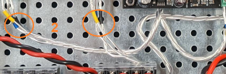
Hopefully the novice in me follows your question. There's two loop breakers circled in red you can see in the attached image. Each breakers connection to chassis is circled in yellow. Loop breaker on the left has a short wire to the copper chassis grounding lug which then goes to IEC inlet ground. On the BTSB loop breaker on the right, input commons are the black wire going into the terminal block as that would reflect pin 1 on an XLR input, it then runs through the loop breaker before going to the chassis ground. I tried to simulate figure 5 from https://sound-au.com/earthing.htm as best I could in regards to the loop breakers.
Previously I have tried pulling the black wire from the terminal block pin 1 and used an aligator clip jumper to connect that to the left loop breaker as well as directly to the copper chassis grounding lug but I was unable to hear a difference.
Cable shields not used for signal return are connected at only one and and tied to the chassis through a loop breaker, so perhaps I have done at least one thing right. 🙂
Attachments
D
Deleted member 148505
1a) I see, looks like the BTSB has the connection the chassis ground already by a loop breaker connected the the screw mount on the chassis. Yes they are essentially the same.
1b) is the cable shield connected to the chassis earth or on power supply 0 volt line? (not familiar with the loop breaker module that you've used) You can directly connect the shield of the cable to the chassis ground (put it on the screw mount of BTSB buffer).
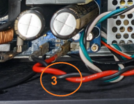
2) Yes I can also see that the wires from the buffer going to Sylph-D modules are directly passing through the AC line, so it will definitely pick up the AC hum (attached pic).
3) I see, SMPS600RS has a Cat II isolation so no earthing directly from the module.
Have you tried to connect the power supply zero volt line to the loop breaker just like below? Try to tap it on the bulk caps between power supplies and the modules. Instead of having the power supply ground float.

1b) is the cable shield connected to the chassis earth or on power supply 0 volt line? (not familiar with the loop breaker module that you've used) You can directly connect the shield of the cable to the chassis ground (put it on the screw mount of BTSB buffer).
2) Yes I can also see that the wires from the buffer going to Sylph-D modules are directly passing through the AC line, so it will definitely pick up the AC hum (attached pic).
3) I see, SMPS600RS has a Cat II isolation so no earthing directly from the module.
Have you tried to connect the power supply zero volt line to the loop breaker just like below? Try to tap it on the bulk caps between power supplies and the modules. Instead of having the power supply ground float.
Attachments

Last edited by a moderator:
Yesterday I put the shields of inputs on the BTSB ground screw. I also swapped to shielded inputs between the BTSB and TPA3255 amps, I placed a brass standoff between the BTSB outputs and terminated the shields there.
I have not yet tried terminating the 0v line of the PSU to the loop breaker, but will try that soon. For reference I found the loop breaker here https://theslowdiyer.wordpress.com/2015/07/29/project-files-little-helpers-ground-loop-breaker/ and had some PCBs built. Once I tap 0v to the loop breaker I will report back.
I've made some massive headway on the issues on my problematic receiver. It appears that any HDMI cable connected between my HTPC and receiver causes this problem, I suspect it has something to do with using a Pico PSU which is a a DC-DC PSU thus the HTPC chassis has no ground. More experimenting to come on that.
D
Deleted member 148505
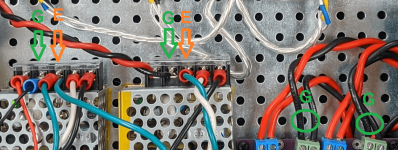
I think you need to rewire these mini SMPSes, -V (0V) should go to ground of loopbreaker (green G label on attached pic), and chassis ground should go to earth of loopbreaker (or connect it directly to the chassis earth beside it, orange E on the attached pic). Currently, I can see that the SMPS chassis gnd is connected to the ground of the loopbreaker module. It should be wired to earth gnd.
Then -V (0V) of SMPS600RS should go to ground of loopbreaker.
If chassis metal plate is not painted and has good connection, you can directly bolt the earth gnd of the modules into it.
Attached pic
Then -V (0V) of SMPS600RS should go to ground of loopbreaker.
If chassis metal plate is not painted and has good connection, you can directly bolt the earth gnd of the modules into it.
Attached pic
Attachments
Last edited by a moderator:
Thanks I will try that out likely tomorrow. You can see some kapton tape on the side of one of the mini smps, both have the bottom and side covered in kapton tape, and they sit on top of nylon washers mounted with nylon screws. My fear was that since the smps frame terminated to the point you have marked with the orange E, there could be a loop with terminating the chassis to the steel plate and having the earth wire connected to chassis ground.
https://www.meanwell.com/Upload/PDF/RS-15/RS-15-SPEC.PDF
These are the modules, 12v versions
When assembling the case all parts of the chassis were sanded in an area to ensure the full chassis and steel plate were "one metal piece". If I were to remove the kapton tape, and washers, then mount the meanwell SMPS directly to the steel plate would I be able to skip the need of a short wire from the orange E to the steel plate?
Last edited:
D
Deleted member 148505
Hmm either way will do as long as there's a good connection between the metals. Earth terminal of mini SMPS to sanded earth chassis should have a lower impedance connection.Thanks I will try that out likely tomorrow. You can see some kapton tape on the side of one of the mini smps, both have the bottom and side covered in kapton tape, and they sit on top of nylon washers mounted with nylon screws. My fear was that since the smps frame terminated to the point you have marked with the orange E.
https://www.meanwell.com/Upload/PDF/RS-15/RS-15-SPEC.PDF
These are the modules, 12v versions
When assembling the case all parts of the chassis were sanded in an area to ensure the full chassis and steel plate were "one metal piece". If I were to remove the kapton tape, and washers, then mount the meanwell SMPS directly to the steel plate would I be able to skip the need of a short wire from the orange E to the steel plate?
I just realized that BTSB buffer has an isolated supply so if you connect the ground of mini smps and gnd of connex smps, it will nullify the isolation. Try to either connect mini smps to gnd, or connex to gnd and vice versa. (to the 0V line of ground loop breaker)
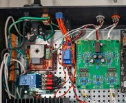
After mulling about, I decided to remove the loop breaker module. I've attached an image of my current build. When removing the loop breaker and testing out resistances, I found that the connnection between the steel plate of the chassis and the earth pin on my power inlet was not ideal and causing some resistance, as you can see in the image I placed a brass stand off where the loop breaker was to connect to the ground lug. I've also grounded the mini SMPS' directly to the chassis with a short cable as suggested, everything right now is dead silent and I am absolutely happy as can be. I may at a later date return to the loop breaker module with some proper wiring and test tapping the mini SMPS into the 0v side of the loop breaker, but for now I am happy without it as it shouldn't be a necessary device in my build.
I want to extend my sincere thanks for all of the help, I learned some valuable lessons on grounding with this project. Yesterday I had the revelation that the reason I never had these issues with my previous build was because the only object with a path to earth was the metal chassis itself, everything else was floating, therefore no loops.
I want to extend my sincere thanks for all of the help, I learned some valuable lessons on grounding with this project. Yesterday I had the revelation that the reason I never had these issues with my previous build was because the only object with a path to earth was the metal chassis itself, everything else was floating, therefore no loops.
Attachments
D
Deleted member 148505
Nice to hear that you resolved the hum problem.
Make sure that the power is turned off if you remove or put the PFFB jumpers. There's a possibility that the input pins of the chip will get toasted (don't ask me how I know 🤦♂️).
THD+N vs Power graph of that module is actually good, -94dB at 5W(4ohm), -97dB from 10W to 40W(4ohm), then 95dB up to 200W(4ohm) before clipping. Unlike other amps where their THD+N degrades after 20W. I might send a sample next year to Amir (if he allows)
- Home
- Amplifiers
- Class D
- JLE Sylph-D400M TPA3255 Issue with Hum and Grounding