Got this 500/5 here in front of me, appeared to be in fairly good condition. All gate resistors check OK, Power Fets, Diodes and Output Fets are all OK. Once the remote wire is applied the voltages on the auxiliary supply all start to come up but stop about 3-5 volts short before the amp draws excessive current and the process starts again. The amp pulses approximately every second like this until the remote wire is disconnected. The main power supply produces 2 partial pulses before the amp starts drawing excessive current.
All diodes, and power supply fets are currently removed. I've looked over the board very closely and the only thing I found was a resistor and diode near the power supply board appear to have gotten pretty hot as the solder here had clearly been overheated, Both components were pulled and the resistor is in tolerance and the diode still functions properly. Swapped the power supply driver board with a known good one thinking the 3525 chip had failed and it didn't change the amps behavior.
This one has me a bit stumped.
(found that I had a bad connection to my power supply and the voltage was dropping causing a reset on the amp)
However, with the power supply FETS and diodes out the amp still draws approximately 2 amps which I believe to be a bit on the high side. The power indicator led appears to flicker a little but the voltage on that pin never comes up high enough to illuminate it.
Last edited:
Measure the DC Voltage across the LED. It could be defective.
Does the transistor for the low voltage supply quickly get too hot to touch?
Does the transistor for the low voltage supply quickly get too hot to touch?
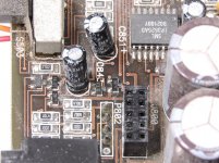
No, the only components getting hot are the 33ohm resistor shown in the attached photo, everything else seems to be about the normal temperature from what I recall on the last 500/5. I did however stumble across a transistor that appears to have been replaced or at least someone attempted to solder on it, I can't make out the part number but it checks defective. I couldn't imagine this causing the amp to draw excessive current though.
 resistor has been hot enough to damage the solder joints and cause most of the color bands to rub off when touched. the diode also appeared to have been hot at some point. both joints were overheated and making poor connection, removed them, cleaned up the holes/leads and put them back.

Do you happen to have a photo of this area that would be useful for getting a transistor part#, perhaps its similar in a 500/1?
The capacitor was removed for getting the partially solder transistor out and for the photo. Also, the led checks ok. The voltage to the display board however varies from 1 volt up to about 2.5 volts and it varies when tapping on the pcb so I would assume I have some internment connections to trace down.
Last edited:
I had to clean it to get it that good. I think is was in a flood. There's a fair bit of corrosion.
I picked up a 250/1 and a 300/4 that way, I figured they would be good for some parts. Got them for basically free.
On the F3 transistor I refrenced that to a MMBC1009F3 which I'm not finding anywhere. What is your go to source for cross referencing parts or is it safe to use any non transistor in this location with similar voltage ratings?
On the F3 transistor I refrenced that to a MMBC1009F3 which I'm not finding anywhere. What is your go to source for cross referencing parts or is it safe to use any non transistor in this location with similar voltage ratings?
Perry, I beleive you are correct after looking at it a bit closer. It appears the pad for pin 2 goes to nothing. Any ideas of what this circuit might belong to?
I would imagine this would not be the cause of the excessive current draw. I'm going to pull all the driver cards and make sure there is nothing on that end being driven with the +\-43 volt supply that's causing the current draw. Also, I'll look over all the vias to make sure I have good connection everywhere.
Perry, would it be safe to say all the op amps on the audio input board should be running cool to the touch after a few minutes of having the amp powered up? I have on in particular that is getting fairly warm, not 2 amps worth of heat but warmer than I would think it should be. I'll upload a photo in a bit.
Had a little bit of time to sit at the amp tonight Q810 does get pretty warm after it's been powered up for a minute or two. The 10 pin connector from the main board to the preamp board only has one negative voltage present and it's at the same voltage as the negative opamp supply voltage.
Perry, would it be safe to say all the op amps on the audio input board should be running cool to the touch after a few minutes of having the amp powered up? I have on in particular that is getting fairly warm, not 2 amps worth of heat but warmer than I would think it should be. I'll upload a photo in a bit.
Opamps are being heated from the 33ohm resistor below them on the main board, I'd say it's safe to say that nearly all 2 amps are being burned in this resistor. Would that indicate q810 is not working correctly?
I think that's part of a snubber circuit. You can expect large resistors to operate at high temperatures.
Is Q810 overheating?
Is Q810 overheating?
Q810 runs fairly hot. In comparing the waveforms on the yellow transformer pins mine are not nice and square like they are for the 500/1. This amp makes a stair stepped wave that does not really resemble what is shown in the tutorial.
It's actually a mosfet with part number 65N06. The solder appears original. On the 500/5 should there be a negative voltage present on the 10 pin header at location 2?
I'm not sure I understand the 'it's actually a MOSFET' part of the statement. FETs are transistors.
I don't know about the voltage. I don't think I have any notes for that.
I don't know about the voltage. I don't think I have any notes for that.
- Status
- Not open for further replies.
- Home
- General Interest
- Car Audio
- JL Audio 500/5