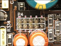
I resoldered the power and ground terminal blocks to the board .
I also touched up some other solder connections and unplugged the preamp board and put in back in the amp several times .
Problem I’m having is if you gently tap the amp it will shut off then power back up .
Is there a common issue with these ?
I also touched up some other solder connections and unplugged the preamp board and put in back in the amp several times .
Problem I’m having is if you gently tap the amp it will shut off then power back up .
Is there a common issue with these ?
GENTLY rake the rows of header pins on top of the preamp board with a non-conductive probe to see if you can make the amp shut off (or cause ANY problems). Rake both directions.
If you find any that are sensitive to touch, you need to add new solder, desolder and then resolder. Just adding solder often won't remove the layer of oxide that developed in the bad solder connection which can cause the connection to fail again.
Push on various parts of the main and preamp boards to see if you can make the amp shut off.
I did everything you suggested and the amp still does the same thing .
It will power up slightest movement and it shuts off
It will power up slightest movement and it shuts off
Which terminals on the LM324 near the power terminals change when it shuts down?
It's odd that none of that made a difference but a slight movement causes the problem.
Does the amp shut down when you move the wires?
It's odd that none of that made a difference but a slight movement causes the problem.
Does the amp shut down when you move the wires?
Now I can’t get it power back up at all .
On the 10 pin header nearest 324 I bet the following
Working left to right starting with the bottom left pin
Pin 1:0.00
Pin 2:0.00
Pin 3:0.00
Pin 4:0.00
Pin 5:0.00
Pin 6:13.90
Pin 7:0.00
Pin 8:0.00
Pin 9:0.35
Pin 10:0.00
On the 10 pin header nearest 324 I bet the following
Working left to right starting with the bottom left pin
Pin 1:0.00
Pin 2:0.00
Pin 3:0.00
Pin 4:0.00
Pin 5:0.00
Pin 6:13.90
Pin 7:0.00
Pin 8:0.00
Pin 9:0.35
Pin 10:0.00
In post 5 that’s the order I did when i posited the voltages
The voltages on the 324
Pin 1:0.00
Pin 2:3.59
Pin 3:0.53
Pin 4:13.90
Pin 5:0.54
Pin 6:4.97
Pin 7:0.00
Pin 8:0.00
Pin 9:5.56
Pin 10:10.16
Pin 11:0.00
Pin 12:3.57
Pin 13:0.32
Pin 14:13.67
The voltages on the 324
Pin 1:0.00
Pin 2:3.59
Pin 3:0.53
Pin 4:13.90
Pin 5:0.54
Pin 6:4.97
Pin 7:0.00
Pin 8:0.00
Pin 9:5.56
Pin 10:10.16
Pin 11:0.00
Pin 12:3.57
Pin 13:0.32
Pin 14:13.67
On the 10 pin connector, you should have 12v on terminal 3. That's the remote input. Confirm that the voltage is reaching R895 behind the PS driver board, that the resistor is within tolerance and that the solder connections are OK.
- Home
- General Interest
- Car Audio
- JL Audio 1000/1