have a marine JL amp thats not working well.
looks like 3 channels aren't working save for 1 working channel.
I have a familiarity with electronics, and actually have a HP regulated power supply with current limiter, and a DMM. this is my first attempt at this amp.
powers on, green light, 1 channel works. rest are dead. i had tested input sources at the rca and all channels have input.
concluded then, that the power supply is ok, since at least 1 channel is working and thought the output power transistors would test bad, but after testing in diode mode, the power mosfets tested ok.
so i'm at crossroads on where to look now.
what part of the circuit would kill 3 channels other than the power mosfets
With the amp connected to a signal source and speakers, operate all pots and switches through their entire range for the channel with signal/speaker. Do you ever get anything out of the dead channels?
good idea. with amp connected to regulated power supply, green light on, rca jacks receiving audio from verified source, and speaker connected. ran the pots up and down, and used contact cleaner on all switches.
only 2 output mosfets get warm, rest are stone cold. diode test on gate/drain shows 0.5v drop and open on reverse. all output resistors read 87ohms.
took 2 IRF-540PBF mosfets out (not the warm ones) and tested out of circuit ok.
however, it appears that my hp regulated power supply cannot hold 12.5V with amps limited to 0.5a. it drops to 6v unless I up the amperage to 1.5a. I am attempting to assess why. is that because there is a short somewhere pulling down voltage? I'm not understanding this.
sowith everything connected, green light on, only 1 channel passing sound out of 4. i dont want to just go start replacing output mosfets but just scratching my head right now.
my hp regulated power supply shows voltage drops seeems to drop voltage
0.5a may not be enough and may cause the amp to trigger the low-voltage protection.
The 'FET' that are getting hot may be the regulators.
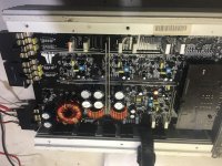
Post a photo of the inside of the amp.
The 'FET' that are getting hot may be the regulators.
Post a photo of the inside of the amp.
got green power light briefly
gah. i so want to get to the bottom of this.
so i replaced the IRF540 transistors and the IRLZ44N mosfets.
now...where before the regulated power supply could not hold 12v, this time it did.
AND i got a green power light. woot. although short lived.
everything was heatsinked up, and unit was holding 13v and 1.7amps steady.
when I noticed the green light went out. no smoke. BUT the windings on the T1 were hot as hell, i could not maintain contact and nothing else was hot. earlier i had tested for an open, but of course, thats not too likely, but i did anyway. this is all new to me and i'm using as much observed evidence and logic as i know how here. I'm thinking that something beyond the T1 is grounded? and pulling hard on the T1? I don't know where to continue from here.
Attachments
I replaced 14 in all 6-IRF540, 6-IRLZ44N, 1-TIP41C, and 1-TIP42C.
ok...i also replaced 2 resistors that really did not need replacing.
i had pulled a couple caps and they checked out ok and checked every diode i could identify
I've cleaned switches, and studied the board under a swivel arm magnifier lamp and bought and read a book called "How to fix anything electronic". and I'm stumped... but i did have a green light - fleeting as it was.
i guess to directly answer your question, i believe i did replace all 6 driver transistors. Those were the IRLZ44N's. Also, i put mica(sp?) between the transistors and the heatsink with a silver arctic thermal compound on all sides.
Are you sure that the original FETs were IRL?
The FETs that you replaced are the power supply FETs. The driver transistors (I think) are Q1, 2, 9 and 12. The PNP drivers commonly fail when the power supply FETs fail.
The FETs that you replaced are the power supply FETs. The driver transistors (I think) are Q1, 2, 9 and 12. The PNP drivers commonly fail when the power supply FETs fail.
Well Perry... You were absolutely correct.
The originals were IRF's not IRL's. I purchased and installed the wrong replacement.
There's a good lesson for me here.
Thank you very much for offering your insight. I'd of been looking everywhere else.
...back to digikey...
i'll update y'all in a few days.
The originals were IRF's not IRL's. I purchased and installed the wrong replacement.
There's a good lesson for me here.
Thank you very much for offering your insight. I'd of been looking everywhere else.
...back to digikey...
i'll update y'all in a few days.
solder pads missing
I feel like i'm headed down the rabbit hole here.
Some of the solder pads came off the board as i was removing the transistors.
please see pic.
when i solder on the replacements, will they make good contact with the board now?
i did try searching for any thread here regarding the pads and i remember reading something from Perry but could not re-find it.
Attachments

If you look carefully, you'll see that there was no trace connected to the pads on the top of the board. Confirm that there is a trace connected to the missing pads on the bottom of the board. If there is, solder on the bottom. Since there may be other damage, solder all connections on top and bottom of the board for all remaining pads.
- Status
- Not open for further replies.
- Home
- General Interest
- Car Audio
- JL AMP M4500 Troubleshoot