Actually i2s signals get reclocked two times. First by SN74ABT273 timed by the masterclosk in the DAC, then they get transferred to the DAC and processed through SM5842 and then again recklocked by SN74ABT574AN. You know I did compare the sound of my system with several CD players and the sound of my DAC is quite pleasant to listen to. I guess the sound would be very bad if the situation that you described were really true. Can I ask you how a FIFO should be used?
OK, checked the datasheet, so SM5842 has a 1 sample FIFO. I presume it is activated in your DAC ?... Pin 12 of SM5842 named SYNCN should be set to HIGH.
> Can I ask you how a FIFO should be used?
This article explains clock domain crossing :
Understanding clock domain crossing issues | EE Times
As you see, it is quite subtle. When doing it inside a FPGA for example, the easiest solution is to instantiate a known-good primitive to handle it, like a small FIFO.
In your case, both clocks are synchronous, but not phase-aligned, and they could also drift by a few nanoseconds (or tens of nanoseconds) depending on what your various PLLs are doing (in the soundcard and in the DIR9001).
Since SM5842 already includes a small FIFO to absorb this drift, and we can assume it is properly designed, then the first reclocking using a flop is either useless, or liable to cause issues, depending on the clock frequency versus bitclock frequency. If MCK is several times BCK then it should be okay.
What is the frequency of the clock being sent from DAC to your SPDIF board ?
Also a 74ABT chip isn't ideal for this... makes lots of noise...
Pin 12 of SM5842 is not connected. So I presume that means high? The frequency of the clock in the DAC is 33 Mhz and then it gets divided by two and 16mHz is sent to the sound card for synchronisation of the card. The frequency of the bitclock is about 2mHz according to the datasheet for SM5842.
Since the frequency of MCK is 16mHz and BCK is about 2 mHz then it means that MCK is 8 times faster than BCK. Hence, I believe that all these fluctuations in PLLs could not create any problems. Do you agree with me?In your case, both clocks are synchronous, but not phase-aligned, and they could also drift by a few nanoseconds (or tens of nanoseconds) depending on what your various PLLs are doing (in the soundcard and in the DIR9001).
Since SM5842 already includes a small FIFO to absorb this drift, and we can assume it is properly designed, then the first reclocking using a flop is either useless, or liable to cause issues, depending on the clock frequency versus bitclock frequency. If MCK is several times BCK then it should be okay.
Datasheet says SYNCN pin has a pullup, so it should be in the right mode.
MCK being much faster than BCK means that reclocking on the SPDIF board should not have metastability issues (worst case data is delayed by 1 MCK but that should be OK) however this first reclocking is still useless since it is duplication of a job done by SM5842 😉
Now, if you want real answers instead of unreliable listening tests, you could measure the jitter at the DAC output...
Well, I guess, I would need expensive equipment to measure jitter at the DAC output. Thank you for opening my eyes about uselessnes of the first recklocking. It should be noted perhaps that I have a PCM-63 DAC which does not use MCK. It only uses BCK as well as 2 remaining I2S lines which get recklocked. What can you tell me about statements by some people who say that jitter can be somehow transferred through a propely designed recklocking circuit? I believe this is impossible in case of properly designed reclocking ciruits. Is this correct? Can you give me a link to any articles about it?
You can measure jitter just fine with a soundcard... You won't be able to measure lower than the soundcard's jitter floor of course, but at least it will tell you if your DAC has more (or less) jitter than the soundcard !
Usually soundcards don't have much data-dependent jitter like SPDIF has, so they're good enough to spot crap from SPDIF decoders misbehaving.
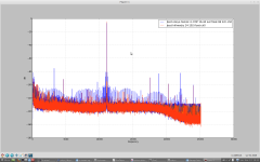
For example, my E-MU 0202 USB (which is mostly crap) has no trouble demonstrating this ONKYO TX-NR 905 receiver's SPDIF handling circuit is world-class crap (see attached image).
> I believe this is impossible in case of properly designed reclocking ciruits.
> Is this correct? Can you give me a link to any articles about it?
Well, properly designed reclocking would :
- make sure timing is correct (ie, edges of clock properly aligned relative to edges of signal to reclock, you can check this on a scope)
- use separate chip for the important signal (BCK or WCK depending on DAC) to ensure no on-chip internal coupling from noisy DATA line
- take care of coupling through power supplies
...AND ESPECIALLY NOT USE 74ABT LOGIC whose current draw depends on the logic value being processed 😉
Why not use 74HC or AHC ? It costs cents and it works just fine !
Anyway, please note that a flop with 10mV noise on its power supply line and its threshold at Vcc/2 will have 5mV threshold noise.
If we have 3ns edges on a 3V3 signal that's 1ns/V therefore our 5mV threshold modulation correspond to ... drum roll... 5 PICOSECONDS... which is extremely low. So you really don't need to spend $$$ on a 1µV noise power supply for your flip flop.... good old 50c LDO works just fine.
A botched-up SPDIF receiver (like in the ONKYO shown here) can easily be 1000x worse. Look at all these spikes! Now, this kind of jitter, no-one has any trouble hearing it. There's a lots of paranoia about jitter and reclocking and stuff but... you gotta measure or you might miss the elephant in the room...
(Example : I implement WM8805. Measure huge jitter on output. It was some noise capacitively coupling into the XTAL oscillator's package. Easy fix when measurement tells you what the cause is...)
Usually soundcards don't have much data-dependent jitter like SPDIF has, so they're good enough to spot crap from SPDIF decoders misbehaving.
For example, my E-MU 0202 USB (which is mostly crap) has no trouble demonstrating this ONKYO TX-NR 905 receiver's SPDIF handling circuit is world-class crap (see attached image).
> I believe this is impossible in case of properly designed reclocking ciruits.
> Is this correct? Can you give me a link to any articles about it?
Well, properly designed reclocking would :
- make sure timing is correct (ie, edges of clock properly aligned relative to edges of signal to reclock, you can check this on a scope)
- use separate chip for the important signal (BCK or WCK depending on DAC) to ensure no on-chip internal coupling from noisy DATA line
- take care of coupling through power supplies
...AND ESPECIALLY NOT USE 74ABT LOGIC whose current draw depends on the logic value being processed 😉
Why not use 74HC or AHC ? It costs cents and it works just fine !
Anyway, please note that a flop with 10mV noise on its power supply line and its threshold at Vcc/2 will have 5mV threshold noise.
If we have 3ns edges on a 3V3 signal that's 1ns/V therefore our 5mV threshold modulation correspond to ... drum roll... 5 PICOSECONDS... which is extremely low. So you really don't need to spend $$$ on a 1µV noise power supply for your flip flop.... good old 50c LDO works just fine.
A botched-up SPDIF receiver (like in the ONKYO shown here) can easily be 1000x worse. Look at all these spikes! Now, this kind of jitter, no-one has any trouble hearing it. There's a lots of paranoia about jitter and reclocking and stuff but... you gotta measure or you might miss the elephant in the room...
(Example : I implement WM8805. Measure huge jitter on output. It was some noise capacitively coupling into the XTAL oscillator's package. Easy fix when measurement tells you what the cause is...)
Attachments
Last edited:
Also, why you should not trust your ears : I tested several cheap canned oscillators in a DAC.
Brand A had the best overall sound, deep black background, very good.
Brand B had a bit blurry sound but overall nice sound and good sizzle in the highs.
Brand C was boring to listen to.
Turns out A has the lowest jitter by far, B has truly humongous random jitter, and C has a DSP-PLL which looks good on paper, has much less jitter than B and only a little more than A. So, don't trust listening tests...
An idea just came to my mind. The frequency of spdif is 2 mHz with something and the frequency of the masterclock that is sent back to the soundcard for synchronisation is 16mHz. How can 16 mHz MCK be conveyed via 2mHz? Does it mean that the masterclock is divided by 8 and then again multiplied by 8 in the sound card? The frequency of bitclock is also about 2 mHz. Could this then lead to a bit error?
I think you mean MHz, not mHz. Multiplying or dividing frequencies is a normal part of many phase locked loops.
- Status
- Not open for further replies.
- Home
- Source & Line
- Digital Source
- jitter of bitclock?