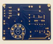
Hi guys. I bought the Kubota high voltage regulator board on ebay and assembled it as labeled on the board but without the tube - used the bypass connection on tube socket. Connected the power supply (270VAC) and got 180Vdc on the output - no load. I started regulating just to see how high could the output voltage get before connecting the load (available I had only 6.12kOhm ceramic resistor, so the current at 300VDC would be at around 50mA - just for test). The output voltage was responding. Then a connection got loose, so I switched it off to fix the wire. When connected back the FU1 fuse blew. After replacing the fuse (I used fast blow instead of slow blow because that's what I had available) there was no output voltage anymore. Troubleshooting revealed all rectifying diodes D1, D2, D3, D4 (FR207) destroyed. Replaced the diodes and checked all other components for damage and proper values (on the attached schematics there is no 330Kohm resistor paralleled to C3 cap - discharge resistor).
Next step was connecting power supply back (270VAC). SAME RESULT - blown the 2Amp fuse and this time only D1 and D2 diode destroyed!?! 😕
Now, I do understand the necessity of a Slow blow fuse (as per instructions, but I had only fast blow available) because of the inrush current for the caps. What I do not understand is the destroyed rectifying diodes (I'm not that deep into electronics)? Does anyone have an explanation?
p.s. You will probably notice that some of the component values on the board (C2, C3, C5) do not match with schematics.
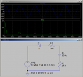
Attachments
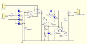

If the board is laid out according to the circuit diagram you have provided then the area around D4 is a problem. The junction above FR207 should not be there.
No, the board is OK, there's no junction above FR207 like on the diagram. It is a bit confusing...
Diodes randomly dying, given they are 1,000V devices sounds like exceeding their peak, repetitive/non-repetitive forward current rating.
https://img.filipeflop.com/files/download/Datasheet_Diodo_FR201-FR207.pdf
I have to admit that in the Offline SMPS world I've never used such fast recovery diodes in that particular location... mains direct in--diodes--dump direct into a big capacitor. Power factor corrected I would expect to use 470uF on a 500W supply with a bridge rated 25A. Ifsm would be nominally huge and I would still incorporate inrush current protection.
That implementation sort of looks like a recipe for toasted diodes. Do not expect the/any fuse to save them. They will go dink first and take out the fuse later.
I hope Jim is not a famous name Jim.
Last edited:
Well, since it did work a couple of initial connections, I'm not ready to giving up on this and I'm firstly leaning on replacing the FR207 with more current capable diodes (like MUR860 or something like that) and see how it goes...
But I guess some inrush current protection would be needed anyway. As a quick solution and before making it proper and final version, to use a powerful resistor as the inrush current would be only a couple of seconds, how about that? Actually, I think I should have some NTC Thermistor which would do the job.
Just remembered I have a variable transformer laying around somewhere, for testing purposes, I mean.
Btw, I'm using 220uF in C3 position instead of 470uF.
Last edited:
Your circuit diagram shows 470uF. The board shows 220uF. Jim's page on ebay shows a 120uF device.
1pc GZ34/5AR4 Kubota Low noise Audio adjust HV regulator for tube amplifier PCB | eBay
Kubota low noise HV regulator w/soft-starting for tube amplifiers PCB !! | eBay
The first one mentions how to use an SMD pad to short out the "inrush current limiting valve." You still need the input diodes which blow up when asked to drive C1.
Just because your diodes do not blow up immediately does not mean you are not giving them a hard time and they are going to go dink the next time.
Elna suggests LTA as a replacement for LPT.
https://www.mouser.com/ds/2/129/catalog_10_11_e-4521.pdf
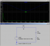
120uF @ 400V has an ESR of 2R8. The board suggests a minimum of 250VAC which is 354 peak.
It's one of those "How lucky do you feel, Punk." things.
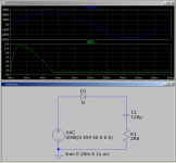
If you switch on at mains zero crossing you get about a single cycle 12.5A peak which is below the 60A Ifrsm for your diode.
If you switch on at mains peak you have 354 volts across 2R8 or about 126A and dead diodes.
I would ask for my money back but if you want to persevere fit the semiconductor diodes. Leave out/short the valve. Leave in the 10R resistor. Move C1 to C3.
I would still be slightly concerned but obviously Jim knows best.
Actually Jim knows bugger all but at least he has a shop on ebay so is probably richer than me.
--
1pc GZ34/5AR4 Kubota Low noise Audio adjust HV regulator for tube amplifier PCB | eBay
Kubota low noise HV regulator w/soft-starting for tube amplifiers PCB !! | eBay
The first one mentions how to use an SMD pad to short out the "inrush current limiting valve." You still need the input diodes which blow up when asked to drive C1.
Just because your diodes do not blow up immediately does not mean you are not giving them a hard time and they are going to go dink the next time.
Elna suggests LTA as a replacement for LPT.
https://www.mouser.com/ds/2/129/catalog_10_11_e-4521.pdf
120uF @ 400V has an ESR of 2R8. The board suggests a minimum of 250VAC which is 354 peak.
It's one of those "How lucky do you feel, Punk." things.
If you switch on at mains zero crossing you get about a single cycle 12.5A peak which is below the 60A Ifrsm for your diode.
If you switch on at mains peak you have 354 volts across 2R8 or about 126A and dead diodes.
I would ask for my money back but if you want to persevere fit the semiconductor diodes. Leave out/short the valve. Leave in the 10R resistor. Move C1 to C3.
I would still be slightly concerned but obviously Jim knows best.
Actually Jim knows bugger all but at least he has a shop on ebay so is probably richer than me.
--
Attachments
Last edited:
You are right, several different values for the same circuit. You say Jim knows bugger all, but he is definitely richer than me, you and several others combined, of this I'm sure! That is why he doesn't care.
Well, I guess I'm the only idiot that didn't see it coming when buying the pcb...and that's why you cannot find any review on it. I'm not bothering with the money back (involving shipping everything back from EU to CHN), too many things could go wrong and I would only get aggravated in the process. But I will send him a "nice" email and wait for his reaction.
Since I'm stuck with pcb's and components, I will try the MUR860 or even MUR3060 combined with NTC thermistor in series after the fuse and see what will happen.
"Move C1 to C3", by that you mean to add it to C3 or to replace C3 with C1?
Whatever fits. Assuming the 10R resistor limits the peak current enough for the diodes to survive at least Ifrsm with some margin then the big capacitor becomes less of a or not a problem. Unfortunately you run into other stuff and I'm not going there because it is hard to critique stuff unless it is almost obviously silly.
Shout Out to someone else for a closer to home high voltage regulator.
Shout Out to someone else for a closer to home high voltage regulator.
- Status
- Not open for further replies.
- Home
- Amplifiers
- Power Supplies
- Jim's Audio Kubota HV regulator