Hello,
I would kindly like your feedback on my problem:
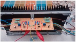
I've purchased lsk170/lsj74 grade B matched jfets from dyaudiostore and mounted them on my F5 Turbo V1 pcb.
See image.
as you can see the jfets can be mounted and unmounted for test (red circle).
- I mount the first pair of lsk170/j74 matched.
- Power ON
- I expet 0 V bias (blu circled resistors 0.47 5W) and closed to 0 V at the output.
- Results are: 0 V bias (OK) and 0.012 V at the output (OK).
I can complete the biasing procedure SUCCESFULLY.
- I unmount the first pair of lsk170/j74 matched
- I mount the second pair of lsk170/j74 matched.
- Power ON
- I expet 0 V bias (blu circled resistors) and closed to 0 V at the output.
- Results are: 0 V bias (OK) and 0.150 V at the output (NOT OK Too high).
I can’t complete the biasing procedure SUCCESFULLY.
If I replace only the second lsk170 (suspect) with the first lsk170, I’ve:
- I expet 0 V bias (blu circled resistors) and closed to 0 V at the output.
- Results are: 0 V bias (OK) and 0.016 V at the output (OK)
I can complete the biasing procedure SUCCESFULLY but obviously they are not matched .
Besides I've an genuine 2sk170BL Toshiba. If I mount this in place of lsk170 suspect,
- Results are: 0 V bias (OK) and 0.010 V at the output (OK)
I can complete the biasing procedure SUCCESFULLY but obviously they are not matched .
What do you think?
So I think that the second lsk170 it’s the responsable.
Biasing procedure it’s obviously according to Pass (God bless him) procedure in the relative article.
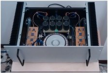
I’m expert on this amplification, I’ve already built one F5 with Toshiba’s Jfets.
See my F5 (normal Not turbo).
Thank you for support.
I would kindly like your feedback on my problem:
I've purchased lsk170/lsj74 grade B matched jfets from dyaudiostore and mounted them on my F5 Turbo V1 pcb.
See image.
as you can see the jfets can be mounted and unmounted for test (red circle).
- I mount the first pair of lsk170/j74 matched.
- Power ON
- I expet 0 V bias (blu circled resistors 0.47 5W) and closed to 0 V at the output.
- Results are: 0 V bias (OK) and 0.012 V at the output (OK).
I can complete the biasing procedure SUCCESFULLY.
- I unmount the first pair of lsk170/j74 matched
- I mount the second pair of lsk170/j74 matched.
- Power ON
- I expet 0 V bias (blu circled resistors) and closed to 0 V at the output.
- Results are: 0 V bias (OK) and 0.150 V at the output (NOT OK Too high).
I can’t complete the biasing procedure SUCCESFULLY.
If I replace only the second lsk170 (suspect) with the first lsk170, I’ve:
- I expet 0 V bias (blu circled resistors) and closed to 0 V at the output.
- Results are: 0 V bias (OK) and 0.016 V at the output (OK)
I can complete the biasing procedure SUCCESFULLY but obviously they are not matched .
Besides I've an genuine 2sk170BL Toshiba. If I mount this in place of lsk170 suspect,
- Results are: 0 V bias (OK) and 0.010 V at the output (OK)
I can complete the biasing procedure SUCCESFULLY but obviously they are not matched .
What do you think?
So I think that the second lsk170 it’s the responsable.
Biasing procedure it’s obviously according to Pass (God bless him) procedure in the relative article.
I’m expert on this amplification, I’ve already built one F5 with Toshiba’s Jfets.
See my F5 (normal Not turbo).
Thank you for support.
Attachments
Although the devices are matched, matching has tolerances, and there is ALWAYS thermal differences. For example, if unmatched JFET with source and gate shorted says, say, 10mA, there are some devices with 9.9mA and other with 10.1mA. Also, if they had matched at say, 30° not necessarily they are matched, at 20°C. Note the values given are examples only.
You can have matched pairs with each pair having a different Idss. You might be near
your limits on the adjustments.
I suggest you measure the Idss of all the Jfets and report back.
your limits on the adjustments.
I suggest you measure the Idss of all the Jfets and report back.
I'm honored for the support of Mr. Pass.
I measured the Idss for all jfets:
-First Pair mached
lsk170 7.10 mA
lsj74 7.18 mA
-Second Pair mached (pair problematic):
lsk170 7.40 mA
lsj74 7.35 mA
if I short the input at the start biasing whith the second pair (suspect) I noticed:
-Offset DC 150 mV NOT SHORTED and
-Offset DC 10 mV SHORTED.
It's normal?
on the contrary for tha others pair shorted or not, the Dc Offset is very similar and closed to zero V.
Thanks for the support.
Your Idss figure should be fine.
I would not expect offset to change with shorted vs un-shorted input.
In the un-shorted case, do you actually have a resistor to ground at the input?
I would not expect offset to change with shorted vs un-shorted input.
In the un-shorted case, do you actually have a resistor to ground at the input?
Mr. Pass
thank you, I really appreciate the support of a legend of Hi-End.
No resistor in the un-shorted input, only schematic F5 Turbo V1 as is.
I think that the second lsk170 is faulty, because the anomaly only occours with this component mounted.
If I try to biasing it, I've more than 1 Volt DC Offset (un-shorted).
If I replace this only with outer jfets (first lsk170 and genuine Toshiba 2sk170BL) I've NOT this problems, biasing it's simple, stable, DC offset closed to zero and the pcb sound wonderful.
What do you think?
No resistor in the un-shorted input, only schematic F5 Turbo V1 as is.
I think that the second lsk170 is faulty, because the anomaly only occurs with this component mounted.
If I try to biasing it, I've more than 1 Volt DC Offset (un-shorted).
If I replace this only with outer jfets (first lsk170 and genuine Toshiba 2sk170BL) I've NOT this problems, biasing it's simple, stable, DC offset closed to zero and the pcb sound wonderful.
Schematic shows R2 of 47K to ground at input.
Yes, could be bad Jfet. If so, it's the first bad Toshiba I've seen.
Whoops, not Toshiba.

- Status
- Not open for further replies.
- Home
- Amplifiers
- Pass Labs
- JFET Problem in F5 Turbo V1