Hello,
First post here, howdy everyone looks like a great forum.
I have the subject amp (JBL CS300.1 mono channel sub amp) that I am trying to repair and need some help, if anyone has a schematic that would be a big help as well. I'm not an expert in electronics, but have played around with them enough to be pretty familiar with the basics, I've also read a bunch of stuff on the BCAE website that helped me fix a two others in the past, both power supply problems.
Here's what I have for tools:
2800W Sorensen DC linear power supply 40V/70A
60Mhz dual trace scope, PC based DSO
Fluke 87 meter
Here's what I've looked at so far:
The amp came to me apparently broken with neither of the 2x20A fuses installed. I inserted a single 10A fuse and powered it up at 12v with the power supply current limit knob set way down. The ps instantly hit the current limit and drew the ps down to 8.8v @ ~.2A, if I increase the current on the power supply the amp acts as if it's nearly shorted out, I raised it to 7A then backed off in fear of blowing something up.
I noticed that if I leave the current limiter on the power supply at or above ~5A and connect the amp it will flash 3 lights on the top slowly 3 times, then they will start flashing very rapidly and I can hear a buzzing noise. A scope on the B+ side (and almost anywhere in the supply section of the amp) shows alot of noise or fluctuation and the caps close to the input power get pretty warm. If I turn the current way down like my first test, the B+ voltage seems stable ~ 9v, with the amp in this state I scoped the power supply section and it seems to be working, I checked the TL494 chip and pins 9 and 10 show a 44% duty cycle ~ 37khz, the positive and negative rail voltages are stable after the rectifiers.
I've taken the board out of the heatsink and visually looked at every component and don't see any obvious signs of damage.
Any help here on what to check or test next would be much appreciated.
Mike
With the transistors clamped tightly to the heatsink, power up the amp where it's stable and measure the voltage across each of the emitter resistors. Do you have one or more that have more than 0.000v DC across them (no load, no signal)?
How much current is it drawing at the point where it's stable?
Do you have any significant DC across the speaker terminals?
Email me if you want the manual.
babin_perry@yahoo.com
How much current is it drawing at the point where it's stable?
Do you have any significant DC across the speaker terminals?
Email me if you want the manual.
babin_perry@yahoo.com
Perry,
Thank you for the response and also the great website you have.
The current when the amp is stable is pretty low ~.2A this is at approx 9v, that is the reading on the power supply, I can measure it more accurately if needed.
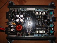
I will take some more measurements like you suggest when I get home tonight and report back. I've attached a pic of the guts for reference. Are you talking about measuring the voltage across the resistors c/t the transistors in the power supply section (these would be the upper and lower left in the pic?
I'll send you an email on the manual, thank you very much.
Mike
Thank you for the response and also the great website you have.
The current when the amp is stable is pretty low ~.2A this is at approx 9v, that is the reading on the power supply, I can measure it more accurately if needed.
I will take some more measurements like you suggest when I get home tonight and report back. I've attached a pic of the guts for reference. Are you talking about measuring the voltage across the resistors c/t the transistors in the power supply section (these would be the upper and lower left in the pic?
I'll send you an email on the manual, thank you very much.
Mike
Attachments
Success
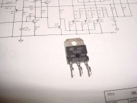
Well, I believe I have the problem figured out. One of the output transistors labeled Q164 on the circuit board which is a TIP36C was shorted between all three legs. I pulled this one out (there are three in parallel) and fired the amp up and it seems to be working fine now, played some light music through it and all was well. Some pics below of the failed part.
Question: Should I just replace this one part, or all three of them as a set? How about the TIP35's on the other side of the board? What else do I need to check on the board with this type of failure? or does the fact that it appears to work fine mean everything else is O.K.
I wanted to give a big thanks to Perry, I've fixed three amps now with the help of you and your website with limited EE knowledge.
Mike
Attachments
You need to replace all 3. Replace the other 3 at your own discretion. If you're ordering from a distributor that cannot guarantee matched date codes, order at least 5 transistors. Generally, they're pre-packaged in either 1, 5, or 10 piece packages. With singles, you may get 5 different date codes. Having matched date codes helps ensure that the transistors are relatively closely matched (which is needed for good reliability).
Check the base resistor for the failed transistor to make sure that it's within tolerance.
Check the base resistor for the failed transistor to make sure that it's within tolerance.
Just wanted to let you all know that I ordered all new output transistors TIP35C and TIP36C just to be safe and installed them the other day, amp seems to be working perfectly. I ordered the components online from Newark, never used them before but I will again they seemed to be very fast shipping and a little cheaper than the others I've used (Digikey, mouser, etc.) all the components had the same date codes as well. Thanks again everyone.
Mike
Mike
- Status
- Not open for further replies.
- Home
- General Interest
- Car Audio
- JBL CS300.1 Help/Schematic??