I'm looking for a Jands J-700 amplifier service manual,if anyone has a copy? I tried Jands of course, I sent them an email saying I'm doing the repair myself,they replied that they don't send them out to the general public? Then asked me where I lived so he could send me to a repairer Grrrr
It might be well worth to give the guys at "Clark Audio" a phone call/email regarding your amp - there's not much they haven't seen/done/repaired/upgraded over the years - they've a website and located in Mt Waverley, Melbourne - very highly regarded.
It might be well worth to give the guys at "Clark Audio" a phone call/email regarding your amp - there's not much they haven't seen/done/repaired/upgraded over the years - they've a website and located in Mt Waverley, Melbourne - very highly regarded.
Thanks for that James,Ill send of an email and see what happens.How did we ever get things done before the internet

Thanks for that James,Ill send of an email and see what happens.How did we ever get things done before the internet
I got onto Dallas Clarke from Clarke Audio,he said Jands don't have a service manual for that model or a schematic that he is aware of? Oh well Ill have to try and figure it out myself.This amp looks like it was put together by a drunken monkey with good soldering skills.Ha!
Sorry that he wasn't able to assist, Ross, and yes, tho Jands stuff back when was pretty basic
Maybe, just maybe it might be a variation of the Leo Simpson circuits that were all the rage back then - those amplifier circuits were also pretty basic but a lot of guys did manage to get them to function at higher power okay - the name they were called escapes my leaky memory - "playmaster" and all that stuff in the forerunner to Silicon Chip mag?
Hope it comes together for you altho. if not, there are plenty of good old 2nd hand power amps in the 'pawn shops' or whatever they're called now, and Geralton is still only a phone call away.
Damn, didn't Jands make a 600 model?
Perhaps it is an 'up-powered' version of the same design?
I don't know about the 600,Ive never heard of that one but I tried to fix a Jands 920 not long ago I was using a hand written schematic that was near on indecipherable.I spent approx $200 on parts before I eventually gave up on it.I was keen to get it going at first because I knew that the 920s were used in the Sydney Opera House in the past.
Jands haven't been in PA manufacturing or service for their old audio gear for many years. JPJ Audio is the successor to Jands former audio manufacturing business.
JANDS and Johnston Audio Merger: Johnston Audio Services is now JPJ Audio while JANDS remains the same.
I don't know whether they still hold service details for Jands legacy products but if they do, you can be fairly sure they won't be handing out anything free to the public whilst ever they have even notional service agreements - even if the products only have historical value.
Jands haven't been in PA manufacturing or service for their old audio gear for many years. JPJ Audio is the successor to Jands former audio manufacturing business.
JANDS and Johnston Audio Merger: Johnston Audio Services is now JPJ Audio while JANDS remains the same.
I don't know whether they still hold service details for Jands legacy products but if they do, you can be fairly sure they won't be handing out anything free to the public whilst ever they have even notional service agreements - even if the products only have historical value.
You would think that Jands would release the schematics of 30/40/50 year old vintage amps even if they did have a service agreement with some workshops?(I cant imagine it wouldn't have been in force when they were sold?) When I was looking for a service manual for the 920 people warned me to just bin it and forget about Jands,they are not worth the bother,stay away from Jands, etc...etc...You don't have to take your Vintage model T Ford back to a certified Ford workshop to get it fixed,you just download the manual.All that Jands has done is give themselves a bad name.I don't know what Jands products and customer service for them are like for the new products now days but if I was in the market for a PA amp I'm certain Jands wouldn't be on my list that's for sure.
I think jameshilljr is probably right that printed schematics were never out there and roadies, local techs etc. just drew up their own if required. BTW, they did make a J600 model before this one.
I suspect that they were similar to other brands or designs that may have been referenced for repair purposes. A couple that I can recall certainly were. There was also a legal copyright problem if the design was too easily compared with other published designs, so referring all the service needs back to the manufacturer or interstate reps. may have been wise.
I'm in regular touch with a local service tech. who, in the day, had to work without printed schematics on Jands, Cord, Wasp etc. products. Perhaps Lenard was an exception. His employer had a heap of service agreements but only a few products, usually imports, were backed up by the distributor forwarding full documentation. As a regional service agency, that was his problem and he solved it the quickest and easiest way at the time. Remember - no scanners, cheap photocopiers, overnight freight, PCs or internet back then. Posted schematics could take weeks to arrive.
It seems shambolic by today's standards for globally distributed products but PA techs generally understood basic solid state amplifier design and these were all very basic local products with limited distribution in the pro. music industry. I could still be wrong but I expect there isn't going to be anything to download anyway.
All is not lost though. Spend a little time drawing a schematic out for yourself - transfer it it to free download sim. program like TI TINA, for example. That can be fun too...well let's face it, repairing an old stager like this is a labour of love - may as well learn something for the effort. 🙂
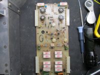
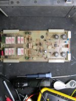
The trouble is Ian that someone has been at it before me, both driver boards are from different models,one board didn't have a DC offset circuit so I built one on it and changed everything around to be the same as the other board.There were three different outputs used without thermal grease on one of the heatsinks? MJ15022,MJ15023. MJ15024,MJ15025. ED204,EB204. some parts had been installed without rhyme or reason,electro caps installed backwards etc..? The thing is and this fairly freaked me out. The soldering was professionally done? I think Ive got it sorted though,I'm waiting on some input transistors then the old dim bulb tester will tell the story? Ive decided to let Jands have the benefit of the doubt so Ive put the voodoo dolls away LOL Thanks for the advice for putting me onto that Tina-TI program Ian its exactly what I need and for SMPS as well, much appreciated.
Last edited:
Well, I wouldn't have touched it in that state, where someone really desperate has mauled it badly and probably many times. I would pull the whole mess and DIY build a known design, 350W amp from the forum or other old schematics, perhaps even from Crown, who have old manuals for download. When you say "didn't have a DC offset circuit" do you mean bias controller or limiter circuit by any chance? Offset is not normally adjustable but it only requires a pot. to substitute for a resistor or 2 in the input stage.
OTOH, I recall that over the years, road amps did get badly treated and badly fixed with whatever spares were available in the crew's toolbox or parts bins. The MJ150XX power transistors only differ in their Vceo, Vbeo figures though, and this means you could, in theory, substitute any types that simply had the same or higher ratings. Mixed parts may not be quite as bad as it looks but then again - if the workmanship sucks too, and no sign of Hfe matching at moderate current, perhaps it is just the work of a desperate person with little knowledge and not enough cash to get the repair done properly.
Unfortunately, unless all the parallel sets of NPN and PNP output transistors are matched properly among each gender for Hfe so they current share, large amps will soon blow when used as they should be - at full power, right on the limiter. These details have been written up in countless PA and big amp repair threads here since the forum began and it is quite expensive to overhaul the stuff properly, even if you DIY.
Moderator Anatech (Canada) made many replies here that were very detailed, textbook methods for repairs and these were legend. Incidentally, there is even a YouTube video on the web showing a curve tracer in use as the guy explains it.
Too bad few of us can afford curve tracers but consistent On-Semi quality allows you to use sets of transistors as they come supplied in their packing tubes, or trays, if TO3. If you have access to a supply of OEM components and can get them to pick the parts in sequence from the one container (at the local agent, distributor) then do this to save time and in the long term, money and client satisfaction. The matching of modern product within its packing lot of 25, 100 etc. will still be very good and better than we can achieve by simple means.
'Glad you like TINA, it works a charm for people like me - too lazy to get immersed in manipulating LT Spice. 😉
This is as many photos that I can upload or otherwise it wont work? I assume that the circuit I added is for DC Offset because that's what the op-amp datasheet says its used for? The central VR is 10k ohms and seems to be the bias controller the other 500 ohm VR is connected to what looks like the temperature transistor. That's why I wanted a service manual so I could work out what was what and and how much to set the bias and temp at? I haven't had time to study the Tina TI yet but it looks like its exactly what I need.
Attachments
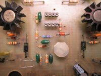
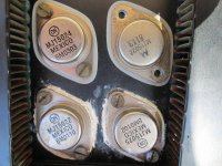
The pics show a lot of replaced components but the matter you mentioned about grease not being used with the T03 washers - Grease is used with mica washers but not with silicone rubber which eliminates grease since its said to conform to the metal surfaces, shown as the 2 upper transistors in the last pic. Typical silicone rubber is not as effective in heat transfer yet while this makes little difference in home audio that may typically output less than a few watts, high power PA is often at maximum and every skerrick of cooling is likely needed, just for reliability. Perhaps it's an availability problem but the original, thinnest possible mica with best quality grease is the way to go.
BTW - The temperature sense transistor or VBE multiplier regulates bias voltage according to the setting of bias adjust pot. located in its base circuit and permitting adjustment of the DC bias of the transistor itself. That's how you identify it. For an illustration, you can just make out the details around VR2 and the small central transistor on the heatsink in this layout diagram of the Silicon Chip Studio 350 amplifier.
Silicon Chip Online - Studio 350 Power Amplifier Module; Pt.2
Silicon Chip Online - Studio 350 Power Amplifier Module; Pt.2
BTW - The temperature sense transistor or VBE multiplier regulates bias voltage according to the setting of bias adjust pot. located in its base circuit and permitting adjustment of the DC bias of the transistor itself. That's how you identify it. For an illustration, you can just make out the details around VR2 and the small central transistor on the heatsink in this layout diagram of the Silicon Chip Studio 350 amplifier.
Silicon Chip Online - Studio 350 Power Amplifier Module; Pt.2
Is there a tutorial or some way I can find out what to adjust V1 and V2 too? I know how to set the bias on some amps using milliamps or millivolts.
Last edited:
'Not sure what V1 & V2 you mean. The 500 ohm value connected to the thermal sensing (Vbe multiplier) transistor will be the bias controller though. Look at the location in your amplifier's circuit to find out what the other controller does, though likely it was originally intended to adjust DC offset as there isn't much else that needs tweaking.
FWIW, and as you have experience of bias setting, a preview of the texts will show that for a given output stage design (usually Emitter follower in double or triple cascade in PA) there is a specific optimal current that ensures least THD. That is measured in mV drop across any of the output pair emitter resistors. As there are 4 pairs, they should all have equal current which means that for a 0.47R resistor where 100mA/output pair is required, within parts tolerance limits, you should read 0.47*0.1 V = 47mV across each and every of the 8 emitter resistors. Total bias current is then 400mA. However, experience tells me that as these are not hi-fi amps, bias will be set a lot lower - perhaps 30 mA ea. only. When setting up, there is no obligation to have bias anyway - just enough is applied to banish noticeable crossover distortion in use.
If you haven't already got a copy, the solid state amplifier design books by Randy Slone (d), Douglas Self and Bob Cordell all cover the whole design of basic amps with a fair bit of attention to the design of the bias controller and appropriate settings. DC offset adjustments are seldom covered in any texts but they are usually simple, straightforward affairs in modern designs.
Though Randy's book is not new or all original, it is intended to inspire DIY projects, so he simplifies and illustrates some areas more clearly so that we can get a grasp on practical aspects sooner. Don't leave home without a copy or at least one the titles.
High-Power Audio Amplifier Construction Manual: 50 to 500 Watts for the Audio Perfectionist: Amazon.co.uk: G. Randy Slone: Books
http://www.amazon.co.uk/Audio-Power...8&qid=1407900376&sr=1-1&keywords=Douglas+Self
Designing Audio Power Amplifiers: Amazon.co.uk: Bob Cordell: Books
There was an online copy of the 4th ed. of Douglas Self's APADH 4th edition at BGaudio club (Bulgaria).(Google it) but periodically gets taken down. (probably copyright infringement)
Not many BJT transistor designs require offset adjustment though. Competent designs come together with no more than 20 mV offset using typical 1% tolerance parts around the input stage and only approximately matched input pair transistors. Really, only Mosfet amplifiers need a DC servo circuit to control their offset though old BJT designs like this may also need a little help when repairs are made. The adjustment is most often only to equalize the input pair current balance, which with the action of negative feedback, is what determines DC voltage at the output of a normally working amplifier.
A larger DC offset is a fault condition - usually blown semis or in this case, perhaps also wrong value components. I don't know exactly what your new offset IC is intended for but if it works as a DC servo, it will be fighting the NFB to do that unless the feedback system is redesigned.
However, don't avoid serious study by looking for just a handful of specific information on these design areas without getting the big picture of how this is all interdependent in a DC coupled amplifier. I don't think you'll find tutorials on audio repair work as such. The topics are discussed on most audio forums in reference to specific models, as you find but being a PA type amp, I'd be looking at forums such as our "Live sound" one because the stuff in this "ss amplifier" forum will take forever to search, even if it's actually relevant or more than just asking for a rare service manual.
Whatever helpful snippets and advice you pick up, you still need to get really acquainted with the underlying principles and topologies of DC amplifiers, otherwise that will become a barrier to understanding whatever you try to do with them. I speak from many years of bitter experience with overconfidently attempting repairs on designs I didn't understand and it always cost me in lots more time and money than the job was worth. Some, I simply had to pass on to experienced pros.
I'm so glad Ive come across you at just the right time Ian! I have another Crown Microtech 1201 and 600 to fix.Gulp! Ill be downloading that book at BGaudio first chance I get.If not Ill buy it.By the way that op-amp for the DC-Offset is CA3160E. Thanks heaps mate.
- Status
- Not open for further replies.
- Home
- Amplifiers
- Solid State
- Jands J-700 service manual