Hi, Jan Peter,
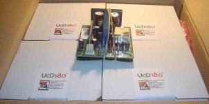
4 modules of UCD180 has arrived here. I wanted to make 4 channel car amp using these modules.
The smps will be unregulated, switching about 30khz pushpull, output from diodes is only C (not L-C). Input = 12V (car supply), output will be asked to you first.
My question is :
1. Since car speakers are most commonly 4ohms, what supply voltage rail you suggest for these 4 modules?
2. Can I make just 1 SMPS to power all these 4 modules, or I must make 4 independent SMPS for each module?
If I can use just 1 smps, can they be connected directly or there is a certain method for using single power supply for powering several UCD modules?
Attachments
If you can make a suitable supply to power multiple modules, do so.
You'd probably be taking a hit in audiophileness, but we're talking car audio anyway right? Imaging and soundstage in car audio is best done with digital delays.
So what it amounts to is what kind of supply can you build.
As per the power output, you'll find the supply voltage in the data sheet of course. What you need to be concerned with is the current capability of your power supply I would think.
You can connect multiple supplies directly, but you can also experiment with certain methods of isolating one amp from the other. Feel free to email me if you don't know what I mean by that.
Hi, Chris,
From some sentences here (I forgot where), I get impression that UCD modules are quite fragile. If I'm not mistaken, someone here burn his UCD module because he touch the SMD parts by hands when it is in operation?
This way, I'm afraid to attach anything, like osciloscope probe, to know what difference if 1 or several UCD modules are attached to 1 supply. They are selfoscilating, if I attach more than 2 modules with the same supply, they won't disturb each other?
Like Chipamps (LM3875, 3886), they specify different max voltage for different speaker impedance. Is that UCD modules takes all speaker impedance the same?
From some sentences here (I forgot where), I get impression that UCD modules are quite fragile. If I'm not mistaken, someone here burn his UCD module because he touch the SMD parts by hands when it is in operation?
This way, I'm afraid to attach anything, like osciloscope probe, to know what difference if 1 or several UCD modules are attached to 1 supply. They are selfoscilating, if I attach more than 2 modules with the same supply, they won't disturb each other?
I don't understand. What does it mean?You'd probably be taking a hit in audiophileness, but we're talking car audio anyway right?
The datasheet is only 1 sheet of paper. It said max voltage, protection voltage (52V), but do not specify what is the best voltage for 4 or 8ohm speakers.As per the power output, you'll find the supply voltage in the data sheet of course.
Like Chipamps (LM3875, 3886), they specify different max voltage for different speaker impedance. Is that UCD modules takes all speaker impedance the same?
Hi,
They're more robust than you can imagine and will survive just about anything you can throw at them that can be considered to fall under the category of normal use.
It just seems to make sense to me that touching the smd components with your finger on a .. for the sake of argument.. "high speed" power switching module, you're going to create all kinds of capacitive shorts. So it's easy not to touch it.
It does use truly discrete drivers after all.
As far as attaching probes, you know what you're doing and you know where they go, if you dont' short anything out with them, what's the problem?
The 52V is your overvoltage threshold so you dont' really want to run that high, you'll also see the recommended voltage, so apply that to get the power you want. They have current protection at I think 10amps. So if you have 4 modules and you want to run them off one supply, then your supply should be potent enough in current capability to handle them all at worst case of 40 amps sustained for whatever period of time.
It may prove to be more advantageous to make four 10amp supplies, I really don't know.
"Is that UCD modules takes all speaker impedance the same?"
Yep, long as they don't run out of current.

I haven't work on it yet. I will post the result/difficulties when I worked it 😀
Is Jan Peter or Mr. Bruno Putzey is not here anymore?
Is Jan Peter or Mr. Bruno Putzey is not here anymore?
They're around I'm sure, but one problem is they're also very busy. Alot of people are just starting new thread after new thread these days because those ever so handy dedicated ones are just "too long" for them to bother with, so they're less likely to spot this kind of question I think.
If you hold off just a little while I expect it's the exact kind of question you might get answered once they release their SMPS 🙂
If you hold off just a little while I expect it's the exact kind of question you might get answered once they release their SMPS 🙂
Embarrassed wince...
I'm afraid I've started a few recently. I hope I'm not making a mess of things. I truly do appreciate the help and try not to post what's already been posted...
😱
Regards,
Tom
I'm afraid I've started a few recently. I hope I'm not making a mess of things. I truly do appreciate the help and try not to post what's already been posted...
😱
Regards,
Tom
hmmmmmm...
@lumanauw,
im currently "upgrading" an AT PC power supply... changing transformer for higher output current @ 12VDC...although, Im having a HARD time understanding HOW to rewind one... darn too hard to understand... I have been winding SMPS with BiFilars, but PC AT, just too hard for me... maybe I need practice...
after that, I plan to build SMPS 12V -->> +/-36V.....I know its much easy to build this one becuase I HAVE MADE ONE myself....
Hi Raff,
If you will build just for powering your 'UcD DIY', just follow my instruction. No problem, just make your winding direction as original and add new half bridge circuit. It shall work as mine. I made more than twice. All of mine works fine.
If you will build just for powering your 'UcD DIY', just follow my instruction. No problem, just make your winding direction as original and add new half bridge circuit. It shall work as mine. I made more than twice. All of mine works fine.
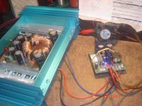
lumanauw said:Testing 1 module on smps. It works, and sounds good even on primitive setup 😀
Is there a trick to get more bass from UCD?
Nice work on the SMPS !! 😀
big ferrite toriod too...... maybe 10A output capacity? I only got 1 here... outer diameter of 1.5 inches.... 🙂
cool!!!
Maybe you can tell a ittle more about the power supply? I'm plannin also an UcD for car audio appplication...l😎
Rob.
Rob.
You can download the pcb files free in my website. Open it with protel.Maybe you can tell a ittle more about the power supply? I'm plannin also an UcD for car audio appplication...l
Hi,
The only weakness of de UcD180 (in this case) are the power fets. These are 100V devices so stay under 50V rail voltage. Power fets usually do not tolerate much over voltage and I have seen many fade away with just under 5% over voltage.
To get most out of the UcD’s in a car, use an inverter with stabilised output to keep rail voltage safe under worst case battery voltage.
Cheers 😉
They're 120V devices. (even the 100V ones).
You keep them safe by ensuring that under worst case conditions, overvoltage isn't exceeded, that's 52V, and you still have a proper margin.
Not so weak after all, are they?
You keep them safe by ensuring that under worst case conditions, overvoltage isn't exceeded, that's 52V, and you still have a proper margin.
Not so weak after all, are they?
classd4sure said:They're 120V devices. (even the 100V ones)
Hmm, that’s new to me. I was told it were 100V devices. But I will look it up, have still some bare modules on the shelf here. Anyway the over voltage protection will trip at 52V. But I suppose it will have some tolerance 😀
😉
Jan-Peter discussed it recently in one of these threads.
The older mosfets used that are rated at 100V use the very same die as that of the 120V mosfet.
The older mosfets used that are rated at 100V use the very same die as that of the 120V mosfet.
- Status
- Not open for further replies.
- Home
- Amplifiers
- Class D
- Jan Peter help