


I have written a 37 page step by step guide with tons of supporting pictures, layouts, BOMs and hints to building your own Leach amp similar to the pictures you see attached. The guide will give you one click links to order every part needed. It provides prices for each component. You will find the the guide only in this thread and supporting documents in the next message and on Google Drive in the link below...
I couldn't upload everything to this thread due to the 1Mbyte size limit so I've provided a link to my Google Drive share below.
https://drive.google.com/folderview?id=0B58oAY4YXWhPUEstcGpKMlJEMDQ&usp=sharing
Charles Robison
View attachment Leach Amplifier Assembly Guide v1.0 _pg1-20.pdf
View attachment Leach Amplifier Assembly Guide v1.0 _pg21-37.pdf
Last edited:
Supporting files for Leach Amp Assembly Guide
I'm attaching the supporting files for the assembly guide here in case the Google drive link ever expires or breaks.
View attachment Leach Amp Building Accessories BOM.pdf
View attachment Leach Amp Chassis BOM.pdf
View attachment Leach Amp PCB BOM.pdf
View attachment Leach Amp Chassis Layout.pdf
View attachment Leach Amp Chassis Measurements.pdf
View attachment Leach Amp ExpressPCB Layout.pdf
View attachment Leach Amp Rear Panel Layout & Measurements.pdf
View attachment PCB files.zip
Thanks!
Thank you very much for opening the thread and giving all information about the Leach amp. I am about to begin the project.
Regards
Roushon.
Thank you very much for opening the thread and giving all information about the Leach amp. I am about to begin the project.
Regards
Roushon.
Well done Charles on your documentation. I have never heard a Leach amp before, how would you compare it to lets say Pass F4 or Aleph J? Is there a cheaper alternative to the cost of the pcb's?
Hi Charles,
Can you kindly post the schematic? I am new and I am not familiar with Leach amp. Is it supposed to be a very good sounding amp?
Thanks
Can you kindly post the schematic? I am new and I am not familiar with Leach amp. Is it supposed to be a very good sounding amp?
Thanks
Neville, I'm not entirely familiar with the Pass F4 or Aleph J but i've reviewed the output stage and in my opinion the Leach amp is a much higher end amp than these. Pass F4 is a class A amp running 50 watts into 4 ohm with two output transistors. Alepha J is running 25 watts (probably into 4 ohms). According to Dr. Leach, if you increase the bias current to run in a similar class A mode, this amp would be 1200Watts into 4 ohms but is not recommended as it cannot dissipate that much heat with the heatsinks in this design (The Leach Amp - Output Stage). The leach amp is an extremely robust and beautiful sounding class AB 200Watt amplifier with 4 output transistors (double the Pass 4 per channel).
As for the PCB cost... well unfortunately i have not found a cheaper option unless you are willing to build with friends or find others on this forum to divide the cost. It is cheaper per board to build 10 at a time than just 2.
As for the PCB cost... well unfortunately i have not found a cheaper option unless you are willing to build with friends or find others on this forum to divide the cost. It is cheaper per board to build 10 at a time than just 2.
Alan0354,
you can find the schematic at the following link: http://users.ece.gatech.edu/mleach/lowtim/graphics/ckt.pdf
let me know if that doesn't work and i'll post the schematic directly.
Also, absolutely a fantastic sounding amplifier. Extremely robust, elegant and most importantly sounds awesome! I do recommend running a pre-amp into the leach amp because it performs best with a high voltage, clean input.
Nice build , man.
The leach does indeed sound nice.
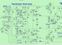
My big brother "spooky leach" is quite the jaw dropper.
Never seen the "modern" TO-3p version of the original.
OS
The leach does indeed sound nice.
My big brother "spooky leach" is quite the jaw dropper.
Never seen the "modern" TO-3p version of the original.
OS
Alan0354,
you can find the schematic at the following link: http://users.ece.gatech.edu/mleach/lowtim/graphics/ckt.pdf
let me know if that doesn't work and i'll post the schematic directly.
Also, absolutely a fantastic sounding amplifier. Extremely robust, elegant and most importantly sounds awesome! I do recommend running a pre-amp into the leach amp because it performs best with a high voltage, clean input.
Thanks
Thanks os.
It was quite a bit of work because i had to layout the PCB by hand to make the TO-3p package work. I used micrometers and my old burned up leach 4.5 board to layout the new design. I think it really cleaned up the appearance.
It was quite a bit of work because i had to layout the PCB by hand to make the TO-3p package work. I used micrometers and my old burned up leach 4.5 board to layout the new design. I think it really cleaned up the appearance.
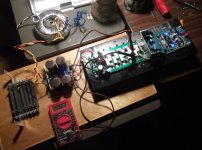
Here's a version of Leach's amplifier using ThermalTrak NJL3281/1302 perforated emitter (fast and linear) output transistors I've only just gotten to the listening stage. First one I've built with plastic case devices and toroids. Rails are 54 vdc and about 60,000 uF of capacitors. I wanted a much smaller chassis than my original amplifier and I think this one looks better.
I've been building Leach's design since the 70's and can attest to the good quality of the sound and reliability. Well, mostly; I had a major failure that cooked a woofer thanks to some bad judgement on my part; I had the bias turned up for minimum distortion and I think the bias diode string went open circuit after years of being toasted. I'll use the recommended fuses and less bias in the future.
I typically measure THD at .005% at one to ten watts over most of the audio range, typically rising with power and frequency.
Attachments

Thanks os.
It was quite a bit of work because i had to layout the PCB by hand to make the TO-3p package work. I used micrometers and my old burned up leach 4.5 board to layout the new design. I think it really cleaned up the appearance.
You need sprint layout and a toner based printer.
By hand - quite the updated layout - that's why I never saw it ???
The Leach can go to new levels with a some 21'st century updates.
(below 1) is a leach with hawksford VAS , CCS's , and a 2 device Vbe EF3
- no diodes to burn - 1mv thermal stability. (outputs as drivers !!)
(below 2) is the 5 pair / 400w leach.
I only have 2 pair outputs now (need mica). Does .002% 20k 200w.
It does sound good at 100w ( 2 pair is 100w @ 8R - 5 pair 250w).
If you want your 2 pair setup to "do the watts" , Semelab has the
outputs - http://products.semelab-tt.com/pdf/bipolar/MG6330 MG6330-R.pdf
Those would be drop in replacements , and you would really be 200 8R/300 4R.
Equals about 4 pair typical fairchild/ON semi current ratings .
OS
Attachments
Hello ,
Leach is a great circuit , I am using this modified version with 16 pairs out and it is working great for me with 90-0-90 volt d.c.
Leach is a great circuit , I am using this modified version with 16 pairs out and it is working great for me with 90-0-90 volt d.c.
Hey Damon Hill,
I originally wanted to build with the ThermalTrak transistors so i could keep the design cleaner but at the time I was laying out the PCB and ordering parts i was having trouble sourcing the parts so i had to go with the discrete bias diodes 🙁
I originally wanted to build with the ThermalTrak transistors so i could keep the design cleaner but at the time I was laying out the PCB and ordering parts i was having trouble sourcing the parts so i had to go with the discrete bias diodes 🙁
OS, Agree that Leach could really benefit from an update to take advantage of the advances in silicon. That is a beautiful leach 400w leach board... Great work. I bookmarked the MG6330 in case I decide to update my design in the future.
Vedmitraa, got any pictures you can share? It sounds awesome!
Vedmitraa, got any pictures you can share? It sounds awesome!
- Status
- Not open for further replies.
- Home
- Amplifiers
- Solid State
- I've written a complete guide to building your own Leach Amp 200Wx2 in 2U rack mount