It will probably greatly depend on the filter. And on the transformer. Most filter topologies will affect the unfiltered outputs as well.
I have experimentd with isolation transformers and while there is an improvement on some types of music, overall i was never quite happy. Only used them on phono preamps (500-700VA).
Others, otoh, swear by their isolation transformers. And of course various transformers sound differently.
IME a nice oversized PS transformer beats a combination of two. Digital applications may be very different.
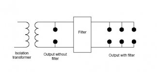
ackcheng: yes that circuit will accomplish what you want, at least from a topology standpoint. Just be aware that transformers and filters include reactive components that can form resonant frequencies when used together. Peaking in the higher frequencies may be occuring if you don't check for it and may actually be more of a hindrance than a help. EMI/RFI/hash filtering can be a tricky business. And no, I'm not an expert..🙂.
another issue I oFten see is people putting a filter before an isolation transformer used for balanced AC, instead of after the transformer. Filters in this application tend to have a balanced topology. Therefore, they are best used on the balanced secondary to cancel, as much as possible, the commom mode noise directed to the ground line. Perhaps people don't put them on the secondary because the transformer is a good common mode filter by itself, as well as a decent rf filter. However, if a "balanced" filter is put on the primary side, common mode noise on the primary side will be diverted to the ground without cancelling it, because the primary is not balanced, thereby creating ground noise. It may be better not to add a filter at all if a good balanced transformer with shield is used. Also, as stated in a prior post, filters can interact and ring if not properly designed.
You've suggested that you'll connect the amp after the isolation transformer...
It is the isolation transformer that is said to degrade dynamics and attack. I think it does myself, but it does nice things for the sound too. I will be listening without mine soon, to see if I prefer it that way...
Capacitor filtering does not ruin the dynamics.
If you want the best allround failsafe option, connect everything bar the power amp after the isolation transformer, and use parallel filtering where it will affect everything, as it will (IME) only do good things for the sound.
Can someone tell us which capacitor values used in combination are suitable to avoid the 'ringing' effect please?
Thanks,
I have tried isolation transformers with my mono block power amps. I could not even use them because it make the power supply transfomer of the amp buzz so loud that I have never heard a transformer make such noise ever before.
Yes, both of them buzz loud, but the amp's transformer was way louder.. May be the amp was drawing too much current for the isolation transformer to handle.
If you want the best allround failsafe option, connect everything bar......
Ditto to what SimontY said above. I have been going through this very issue on my system trying to come to a conclusion as well. The low level front end is better protected than the power amp I think. One must realize that the junk on the power line is a two way street: the power supplies produce their thing and put it out on the mains and it appears as incoming to other equipment, which has it's own problems too. Hopefully, the front end will have internal regulation which can help. One thing you can start off with is putting soft-recovery diodes in all your supplies and perhaps deringing the transformer, if possible. Suppressing emi/rfi sources is a good thing.
One of the reasons I can think of about power amps losing dynamics is simply using an underrated transformer. It needs to be "big" to ensure minimal series losses. Other than that, it should help with their restricted bandwidth, which is btw, exactly what you want. I mean, you want filtering, don't you? If not, then don't use it.
You'll have to ensure that all your grounds are what they should be if you start isolating only parts of your system. Ground loops could be an issue. Just remember resonances can also exist when you start throwing this stuff together.
I've read blurbs while surfing that massive parallel capacitance works and I'd be inclined to agree. Firstly, there is no series component to deal with save for the inherent inductance of the wiring. As for cap values, I've read where 10uf on up can benefit the sound. The mass capacitance acts as a reservoir to the AC mains much like caps are to DC power supplies, I don't see how you can go wrong. One thing I would add is that putting in RF quality caps in parallel with the larger values would probably help. This might be a prime example of where ceramics could be used for good. I've been looking at the ADCOM line enhancers lately, they are reportedly very good and really do filter the higher frequencies. The response curve looks like a lowpass filter. Ebay of course is a place to check. If one were to make a cap reservoir with a LOT of capacitance, then turn on surges may be an issue and you'd have to deal with that.
I don't see how you can go wrong
All that you say makes nice logical sense. Unfortunately once you stop theorising and start experimenting AND listening a lot of the cute little theories fall to pieces. Nothing really explains why a short piece of mains cabling is still audible even after an isolation transformer and filter. What seems to be the problem with most isolation transformers is series resistance rather than limited bandwidth. Still, the two i have at the moment sound completely different although with similar winding resistances.
The parallel capacitor works as an open circuit for the 50-60 Hz but at higher frequencies it works as a short circuit not allowing the higher frequencies to go further into the devices hooked up.
Normally there is also one more capacitor used here connected from neutral to ground.
Look at this link here:
http://www.tnt-audio.com/clinica/mains_e.html
Normally there is also one more capacitor used here connected from neutral to ground.
Look at this link here:
http://www.tnt-audio.com/clinica/mains_e.html
- Status
- Not open for further replies.
- Home
- Design & Build
- Parts
- isolation tranformer with / without filter