I've been wondering what would happen if you isobarically mounted two identical woofers, ported the enclosure for the rear driver, tuned the rear chamber with a useful function, say a bandpass with an upper F3 matching that of the front driver, then low passed the rear driver to reduce its interaction with the front driver.
In effect the system behaves as a single driver into a sealed box above the pass limit and as a ported isobaric below that.
Does anyone see any merit in this approach? More importanly, how would you go about modelling such an approach?
In effect the system behaves as a single driver into a sealed box above the pass limit and as a ported isobaric below that.
Does anyone see any merit in this approach? More importanly, how would you go about modelling such an approach?
Mudge said:I've been wondering what would happen if you isobarically mounted two identical woofers, ported the enclosure for the rear driver, tuned the rear chamber with a useful function, say a bandpass with an upper F3 matching that of the front driver, then low passed the rear driver to reduce its interaction with the front driver.
In effect the system behaves as a single driver into a sealed box above the pass limit and as a ported isobaric below that.
Hmm. If the volume of air between the two drivers is small, it would appear incompressible. This would mean that the doubled mass (two cones) would loose half of its driving force above the crossover frequency and there would be a 6dB drop above this frequency. Maybe this could be used as a baffle step compensation, but I'd simulate it before trying it.
Mudge said:
Does anyone see any merit in this approach? More importanly, how would you go about modelling such an approach?
Do you understand mechanic-electric analogies? If so I could draw you a diagram.
Re: Re: Isobaric/Bandpass 2.5 way hybrid - any thoughts?
That might help, as I tend work in wave equations modelling the system, if only because I'm more comfortable using those, but the equations of motion in this case are ridiculously complicated.Svante said:Do you understand mechanic-electric analogies? If so I could draw you a diagram.
Re: Re: Re: Isobaric/Bandpass 2.5 way hybrid - any thoughts?
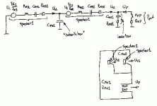
Oki, here we go. I hope I got the box configuration right. Force generators are driven by separate voltages U1 and U2, you will need to apply your filter function to U2. You need to simulate this mechanical circuit and calculate volume flows Us1 and Up. The total volume flow Us1+Up should be inserted in the equation for the point source sound pressure:
P=jw(Us1+Up)*rho0/(4*pi*r)
Sorry about the bad handdrawing. 😉
Mudge said:
That might help, as I tend work in wave equations modelling the system, if only because I'm more comfortable using those, but the equations of motion in this case are ridiculously complicated.
Oki, here we go. I hope I got the box configuration right. Force generators are driven by separate voltages U1 and U2, you will need to apply your filter function to U2. You need to simulate this mechanical circuit and calculate volume flows Us1 and Up. The total volume flow Us1+Up should be inserted in the equation for the point source sound pressure:
P=jw(Us1+Up)*rho0/(4*pi*r)
Sorry about the bad handdrawing. 😉
Attachments
Mudge said:ported the enclosure for the rear driver, tuned the rear chamber with a useful function, say a bandpass with an upper F3 matching that of the front driver,
This bit doesn't make any sense to me.
🙂 sreten.
Re: Re: Isobaric/Bandpass 2.5 way hybrid - any thoughts?
I agree... Hmmm...
sreten said:
This bit doesn't make any sense to me.
🙂 sreten.
I agree... Hmmm...
I admit it doesn't make a whole lot of sense, I'm trying to think of ways to unload the rear wave of a driver below a certain frequency to produce useful output. Just trying to get useful output from a low Q sealed box system below the F3 point, without huge boxes basically.
If I have understood what you propose correctly a local broadcasting authority in Australia did as you suggest about 25-30 yrs ago. There was an analysis in a magazine and I think it went like this. It helps if you think of the new composite driver as a single entity and not two separate drivers. Then what you have is a conventional bass-reflex enclosure with a couple of slight changes. The composite driver has twice the stiffness but also twice the moving mass so the resonance frequency is nearly the same as a single driver. It is not quite identical as you now have the additional mass of the air in between the units which lowers it a little. As I recall they saw the advantages as double the power handling and less colouration as the reflections from inside the enclosure now had to pass through two cone thicknesses rather than one. I guess another approach to take would be to use two different drivers where the inner one was appropriate for the bass and the other better in the mid-range. You might get the best of both worlds then. Jonathan Bright
Sorry Mudge I've just re-read your original post. My last post doesn't address the situation you are suggesting. The speakers I had in mind were just as Svante illustrated. A diagram from you could be helpful as I sense a bit of confusion amongst the viewers. Also, I'm not sure that we are all agreeing about the definition of "isobaric". I suspect that most of us are imagining a pair of drivers buried inside a box and there being one port for the bass output. That would be the most common type that has come to be known as 4th order bandpass. If this is the case then its hard to see how there can be useful midrange output above the upper limit. But I suspect that is not what you have in mind. Are you wanting to have one drive attached to the inner baffle/partition producing bass through a port while the other driver is mounted on one of the external faces of the sealed enclosure and allowing clean midrange frequencies to radiate? That would seem to be an original idea and might produce some interesting results. Jonathan Bright
Thanks Johnathan.
The way I had modelled it was as three systems.
Above the lowpass cutoff, it behaves effectively like a sealed box, the rear driver and the port resisting any cone motion.
Below the cutoff, it behaves like a vented Isobaric, but with the much sharper resonance of a bandpass design.
I've since abandonned the design principle, as the maths required are even more complex than modelling a critically damped transmission line.
I believe I've hit upon a simpler way of modelling that, with a coefficient of cross sectional areas (cone and line to be specific) similar but not necessarily equal to Vas over Vb in an acoustic suspension system. The line length can then be calculated quite simply.
Yeah, it's exactly what I had in mind, and the circuit represents a good analogue of the mechanical forces as electrical components.
The big problem I encountered was tha the phase error in a 4th order bandpass is 180' at port resonance. Therefore for optimal output coupling, between the bandpass section and the main driver, the rear driver has to run out of phase, so it's no longer an isobaric enclosure (I think) but closer to a bipolar design. I start to see why no-one has tried this sort of thing before 😀
😀
The big problem I encountered was tha the phase error in a 4th order bandpass is 180' at port resonance. Therefore for optimal output coupling, between the bandpass section and the main driver, the rear driver has to run out of phase, so it's no longer an isobaric enclosure (I think) but closer to a bipolar design. I start to see why no-one has tried this sort of thing before
😀- Status
- Not open for further replies.
- Home
- Loudspeakers
- Multi-Way
- Isobaric/Bandpass 2.5 way hybrid - any thoughts?