Hi all,
I am trying to build a car audio line driver and need a bipolar power supply for the Op Amps.
I had a Boss AVA1210 Equaliser, which is terrible, but seems to have a tidy and compact dual rail power supply.
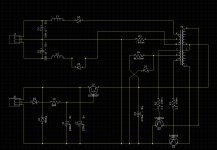
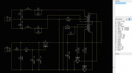
I have traced the circuit out and have come up with the schematic below, the idea being that if the circuit is plausible I will integrate it into the line driver PCB.
Does the circuit look ok, I will be reusing the original parts from the current PCB if possible.
I had wondered about increasing the size of the capacitors to bring down the ripple a bit but wondered whether the oscillation of the circuit depends on their values?
I am trying to build a car audio line driver and need a bipolar power supply for the Op Amps.
I had a Boss AVA1210 Equaliser, which is terrible, but seems to have a tidy and compact dual rail power supply.
I have traced the circuit out and have come up with the schematic below, the idea being that if the circuit is plausible I will integrate it into the line driver PCB.
Does the circuit look ok, I will be reusing the original parts from the current PCB if possible.
I had wondered about increasing the size of the capacitors to bring down the ripple a bit but wondered whether the oscillation of the circuit depends on their values?
Attachments
Hmm.
D3/4 and D5/6 are back to back and will short each other out.
No feedback loop for stabilisation.
There is no isolation between power in and power out.
D3/4 and D5/6 are back to back and will short each other out.
No feedback loop for stabilisation.
There is no isolation between power in and power out.
Thanks Jon.
Silly mistake on the diodes, thanks. 🙂
I shall look for anything that would constitute a feedback loop on the original PCB again.
Is isolation important for low voltage SMPS?
Silly mistake on the diodes, thanks. 🙂
I shall look for anything that would constitute a feedback loop on the original PCB again.
Is isolation important for low voltage SMPS?