Hi,
I have a power amp that I built from a kit a while back. I had been using it with a separate guitar preamp, but the PS supplied with the kit will also run a preamp of its own, so I thought I'd add one. There was no room in the chassis for an another board so the preamp is in a separate project box.
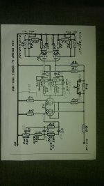
The preamp itself is a plexi clone - identical except for a bypass capacitor and some tiny changes in the component values. I have attached a schematic.
The now-integrated amp works when the preamp volume is set low (for the time being Vol 1 and Vol 2 are on a dual gang pot so can't be set independently). When I turn the volume up I get ugly distortion and the amp seems to lose power, only for it to return a bit later (or as soon as I turn the volume back down).
With no guitar plugged in, the input shorted to ground, and all vols up, I am picking up radio signals. The amp also hums a lot louder than I would have expected (this is with the preamp box about 25cm from the main chassis / power supply). Changing the orientation of the heater wires makes no difference to the hum.
The ground path is:
shield of input cable
to
stage 1 cathode resistors / bypass capacitors
then
stage 1 cathode resistors / bypass capacitors and volume pots
to
stage 1 filter cap
then
stage 1 filter cap and tone pots
to
power supply ground (on the power amp - I believe this is decoupled)
The hum is annoying but my main problem is with the oscillation (if it is that).
Being a clone, the preamp circuit itself is known good. There were no problems with the power amp before, so I'm thinking the issue must be with the way I have assembled the preamp or connected the two.
I don't really want to make any changes to the circuit because I was going for that plexi sound.
I do have long cables back to the PS. I could shorten them a bit but they need to be fairly long just because the preamp is in a separate box.
The pot wires are about 20cm long and the signal out is about 30cm long (unshielded). Again this is pretty much forced on me by the layout.
The preamp board is in an aluminium enclosure that is just big enough, if that makes any difference.
If someone out there could tell me a logical way to go about diagnosing the problem and coming up with a fix, that would mucho appreciated.
Thanks
I have a power amp that I built from a kit a while back. I had been using it with a separate guitar preamp, but the PS supplied with the kit will also run a preamp of its own, so I thought I'd add one. There was no room in the chassis for an another board so the preamp is in a separate project box.
The preamp itself is a plexi clone - identical except for a bypass capacitor and some tiny changes in the component values. I have attached a schematic.
The now-integrated amp works when the preamp volume is set low (for the time being Vol 1 and Vol 2 are on a dual gang pot so can't be set independently). When I turn the volume up I get ugly distortion and the amp seems to lose power, only for it to return a bit later (or as soon as I turn the volume back down).
With no guitar plugged in, the input shorted to ground, and all vols up, I am picking up radio signals. The amp also hums a lot louder than I would have expected (this is with the preamp box about 25cm from the main chassis / power supply). Changing the orientation of the heater wires makes no difference to the hum.
The ground path is:
shield of input cable
to
stage 1 cathode resistors / bypass capacitors
then
stage 1 cathode resistors / bypass capacitors and volume pots
to
stage 1 filter cap
then
stage 1 filter cap and tone pots
to
power supply ground (on the power amp - I believe this is decoupled)
The hum is annoying but my main problem is with the oscillation (if it is that).
Being a clone, the preamp circuit itself is known good. There were no problems with the power amp before, so I'm thinking the issue must be with the way I have assembled the preamp or connected the two.
I don't really want to make any changes to the circuit because I was going for that plexi sound.
I do have long cables back to the PS. I could shorten them a bit but they need to be fairly long just because the preamp is in a separate box.
The pot wires are about 20cm long and the signal out is about 30cm long (unshielded). Again this is pretty much forced on me by the layout.
The preamp board is in an aluminium enclosure that is just big enough, if that makes any difference.
If someone out there could tell me a logical way to go about diagnosing the problem and coming up with a fix, that would mucho appreciated.
Thanks
Attachments
Sounds like you need grid stoppers.
Not an expert on these, but found these links that might help:
Grid Resistors - Why Are They Used?
The Valve Wizard
If you choose the right value, it shouldn't affect the sound, so you might need to experiment a bit unless someone else can chip in.
If it was mine, I would also look at adding some filtering on the inputs just to be sure. Something like 100pF from the junction of R5 & R6 to ground and the same with R3 & R4.
Brian
Thanks. Don't they already have grid stoppers though? There is no path to ground from any of the grids that doesn't go via a resistor, except when the bright vol is on 0, and I get the problem when the bright vol is turned up.
Having said that, only R103 is actually soldered to the valve socket. If I turned the board upside down inside the enclosure I would be able to shorten the wires from the grid pins from roughly 20cm to roughly 5cm. This would make any future maintenance quite a bit harder though, because the components would be on the wrong side of the board (I can't leave it the same way up and turn it around, because of the holes I have already drilled in the box). Is this worth trying, do you think?
Could the length of the wires from the power supply or the fact that the output wire is unshielded be a factor? It would be easier to experiment with that. I did read that it was a bad idea to use shielded output wire though - maybe because of the capacitance of the cable itself.
Its probably either radio interference or oscillation.
I use 10k grid stopper resistors.
Keep wires as short as possible.
For a pre amp I would consider shielded wires for input and maybe output too.
I use 10k grid stopper resistors.
Keep wires as short as possible.
For a pre amp I would consider shielded wires for input and maybe output too.
I'm going to have to start again with another enclosure, I think, and have the grid resistors and C5 on a separate turret board as part of the valve assembly. Is it critical for any other components to be very close to the valves?
I think the problem is RF interference and shielding. The connections between the pre-amp and main amp are especially vulnerable. You might want to try double shielded cables (shielded signal wire encased in another shield). Experiment with grounding the outer shield - both ends; preamp end only; amp end only - and see which works best for you.
I did this for a tube preamp and tube amp once. There was no double shielded cable to be had, so I tied regular single shielded cable to the centre conductor of a coaxial cable and pulled it through so that the shield of the coaxial cable became the outer shield.
A small capacitor across the input terminals (a few pF) should help reduce the RF pickup, if the RF problem persists after you've done the double shielded cable thing.
- Status
- Not open for further replies.