On page 7 of:
http://www.ti.com/lit/ds/symlink/lm3886.pdf
I see no special circuitry to keep current in the transistor set that is not "on" to drive the output.
From page 24:
"The LM3886 is a Quasi-AB type amplifier."
Probably not a class A amplifier.
🙂
http://www.ti.com/lit/ds/symlink/lm3886.pdf
I see no special circuitry to keep current in the transistor set that is not "on" to drive the output.
From page 24:
"The LM3886 is a Quasi-AB type amplifier."
Probably not a class A amplifier.
🙂
Hi,
Its just a very poor "design" with the basics wrong
and what it does has nothing to do with class A.
rgds, sreten.
For single ended class A you need to load the output
with another similar chip configured as a maximum
current source or sink and vastly reduce rail voltage, if
you don't they will expire or shutdown on configuration.
Last edited:
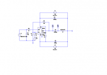
I left the neg. rail for the mute circuit. In a single supply config pin 7 can't be connected to 0V. it is set between pos. rail and neg. rail with a voltage divider of some kind. Because I move the ground towards 0V the mute doesn't work. Use a low current transformer with the same voltage as the positive Rail.
As extra bonus the output signal will not clip if it does crossover.
As extra bonus the output signal will not clip if it does crossover.
Last edited:
The output must run in class B and you need to prevent it from going into Class A at low currents, if that makes any sense. Ci can prevent the DC current returning though the feedback resistors.
why do you believe in the Spice LM3886 macromodel - do you know what's inside?
try again with a discrete transistor power amp sim - one of Bob's examples for instance - look at the output Q individually for Class B operation at amps
try again with a discrete transistor power amp sim - one of Bob's examples for instance - look at the output Q individually for Class B operation at amps
I used LTspice with the LM3886 model by teemuk 21032007 ver.1b.
It has a working mute circuit which is important for this simulation.
It has a working mute circuit which is important for this simulation.
Last edited:
confirming a bad Spice model
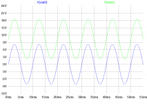
I think you could try this with any Class AB opamp or solid state amp with feedback. By adding neg. offset to the neg. differential input the output goes positive to remove the offset though the feedback loop. Both the positive and negative input show only the input signal as it should be.
I am also still sceptical of this working for real. But theoretically it can.
I am also still sceptical of this working for real. But theoretically it can.
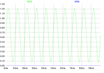
not as you draw it - there has to be DC current flow from the output to bias a CLASS AB chip amp into SE Class A - your circuit doesn't have such a DC path, or current - the Spice model is just wrong
Hi jcx,
Have you a better model. It doesn't have to be for a LM3886. Anything without a mute circuit would make things easier.
The feedback loop has not sufficient DC current to prevent Class A operation. Depending on the offset voltage and feedback current a 80R to 100R resistor was needed in the simulations to achieve this.
just use most any Class AB discrete amp modeled in Spice - there are many - I've posted a few in Bob Cordell's Feedback and Book threads, many others exist
the audioamp.asc included in LTSpice' educational examples files is especially poor, but would show the output Q currents, respond to a external current source
the audioamp.asc included in LTSpice' educational examples files is especially poor, but would show the output Q currents, respond to a external current source
Here are three examples of class A chipamps. Maybe not what you have in mind, but true class A, SE, with chips:
http://www.diyaudio.com/forums/chip...ator-chip-amp-madness.html?highlight=se+class
http://www.diyaudio.com/forums/chip...complementary-version.html?highlight=se+class
http://www.diyaudio.com/forums/chip...ulator-chip-amplifier.html?highlight=se+class
http://www.diyaudio.com/forums/chip...ator-chip-amp-madness.html?highlight=se+class
http://www.diyaudio.com/forums/chip...complementary-version.html?highlight=se+class
http://www.diyaudio.com/forums/chip...ulator-chip-amplifier.html?highlight=se+class
Have you a better model. It doesn't have to be for a LM3886. Anything without a mute circuit would make things easier.
LM1875 spice model:
.SUBCKT LM1875 3 2 4 5 6
* EXTERNAL NODE DESIGNATIONS
* 5 --> - SUPPLY (VEE)
* 4 --> + SUPPLY (VCC)
* 6 --> OUTPUT
* 2 --> (-) INPUT
* 3 --> (+) INPUT
EOX 120 10 31 32 2.0
RCX 120 121 1K
RDX 121 10 1K
RBX 120 122 1K
GOS 10 57 122 121 1.0
RVOS 31 32 1K
RINB 2 18 1000
RINA 3 19 1000
DIN1 5 18 DMOD2
DIN2 18 4 DMOD2
DIN3 5 19 DMOD2
DIN4 19 4 DMOD2
EXX 10 5 17 5 1.0
EEE 10 50 17 5 1.0
ECC 40 10 4 17 1.0
RAA 4 17 100MEG
RBB 17 5 100MEG
ISET 10 24 1e-3
DA1 24 23 DMOD1
RBAL 23 22 1000
ESUPP 22 21 4 5 1.0
VOFF 21 10 -1.25
DA2 24 25 DMOD1
VSENS1 25 26 DC 0
RSET 26 10 1K
CSET 26 10 1e-10
FSET 10 31 VSENS1 1.0
R001 34 10 1K
FTEMP 10 27 VSENS1 1.0
DTA 27 10 DMOD2
DTB 28 29 DMOD2
VTEMP 29 10 DC 0
ECMR 38 10 11 10 1.0
VCMX 38 39 DC 0
RCM2 41 10 1MEG
EPSR 42 10 4 10 1.0
CDC1 43 42 10U
VPSX 43 44 DC 0
RPSR2 45 10 1MEG
FCXX 57 10 VCXX 100
DCX1 98 97 DMOD1
DCX2 95 94 DMOD1
RCX1 99 98 100
RCX2 94 99 100
VCXX 99 96 DC 0
ECMX 96 10 11 10 1.0
DLIM1 52 57 DMOD1
DLIM2 57 51 DMOD1
ELIMP 51 10 26 10 99.3
GDM 10 57 3 2 1
C1 58 59 1e-10
DCLMP2 59 40 DMOD1
DCLMP1 50 59 DMOD1
RO2 59 10 1K
GO3 10 71 59 10 1
RO3 71 10 1
DDN1 73 74 DMOD1
DDN2 73 710 DMOD1
DDP1 75 72 DMOD1
DDP2 71 720 DMOD1
RDN2 710 71 100
RDP 720 72 100
VOOP 40 76 DC 0
VOON 77 50 DC 0
QNO 76 73 78 NPN1
QNP 77 72 79 PNP1
RNO 78 81 1
RPO 79 81 1
VOX 86 6 DC 0
RNT 76 81 100MEG
RPT 81 77 1MEG
FX 10 93 VOX 1.0
DFX1 93 91 DMOD1
VFX1 91 10 DC 0
DFX2 92 93 DMOD1
VFX2 10 92 DC 0
FPX 4 10 VFX1 1.0
FNX 10 5 VFX2 1.0
RAX 122 10 MRAX 1.002000e+03
.MODEL MRAX RES TC1=5e-05
FIN1 18 5 VTEMP 0.875
FIN2 19 5 VTEMP 1.125
CIN1 2 10 1e-12
CIN2 3 10 1e-12
RD1 18 11 500000
RD2 19 11 500000
RCM 11 10 9.75e+06
FCMR 10 57 VCMX 31.6228
FPSR 10 57 VPSX 63.2456
RSLOPE 4 5 1000
GPWR 4 5 26 10 0.02
ETEMP 27 28 32 33 0.219999
RIB 32 33 MRIB 1K
.MODEL MRIB RES TC1=0.00293599
RISC 33 34 MRISC 1K
.MODEL MRISC RES TC1=-0.003
RCM1 39 41 316.228
CCM 41 10 1.59155e-10
RPSR1 44 45 10000
CPSR 45 10 5.30516e-10
ELIMN 10 52 26 10 99.3
RDM 57 10 420.038
C2 57 10 3.4446e-11
ECMP 40 97 26 10 0.5
ECMN 95 50 26 10 0.5
G2 58 10 57 10 9.5e-06
R2 58 10 250.604
GO2 59 10 58 10 32
EPOS 40 74 26 10 0
ENEG 75 50 26 10 0.1
GSOURCE 74 73 33 34 0.04
GSINK 72 75 33 34 0.04
ROO 81 86 0.5
.MODEL DMOD1 D
*-- DMOD1 DEFAULT PARAMETERS
*IS=1e-14 RS=0 N=1 TT=0 CJO=0
*VJ=1 M=0.5 EG=1.11 XTI=3 FC=0.5
*KF=0 AF=1 BV=inf IBV=1e-3 TNOM=27
.MODEL DMOD2 D (IS=1e-17)
*-- DMOD2 DEFAULT PARAMETERS
*RS=0 N=1 TT=0 CJO=0
*VJ=1 M=0.5 EG=1.11 XTI=3 FC=0.5
*KF=0 AF=1 BV=inf IBV=1e-3 TNOM=27
.MODEL NPN1 NPN (BF=100 IS=1e-15)
*-- NPN1 DEFAULT PARAMETERS
*NF=1 VAF=inf IKF=inf ISE=0 NE=1.5
*BR=1 NR=1 VAR=inf IKR=inf ISC=0
*NC=2 RB=0 IRB=inf RBM=0 RE=0 RC=0
*CJE=0 VJE=0.75 MJE=0.33 TF=0 XTF=0
*VTF=inf ITF=0 PTF=0 CJC=0 VJC=0.75
*MJC=0.33 XCJC=1 TR=0 CJS=0 VJS=0.75
*MJS=0 XTB=0 EG=1.11 XTI=3 KF=0 AF=1
*FC=0.5 TNOM=27
.MODEL PNP1 PNP (BF=100 IS=1e-15)
*-- PNP1 DEFAULT PARAMETERS
*NF=1 VAF=inf IKF=inf ISE=0 NE=1.5
*BR=1 NR=1 VAR=inf IKR=inf ISC=0
*NC=2 RB=0 IRB=inf RBM=0 RE=0 RC=0
*CJE=0 VJE=0.75 MJE=0.33 TF=0 XTF=0
*VTF=inf ITF=0 PTF=0 CJC=0 VJC=0.75
*MJC=0.33 XCJC=1 TR=0 CJS=0 VJS=0.75
*MJS=0 XTB=0 EG=1.11 XTI=3 KF=0 AF=1
*FC=0.5 TNOM=27
.ENDS LM1875
how is this useful? - what are this macromodel's capabilities?
does it even show output current in the rails correctly?
I realize the netlists get separated from their schematics over time - but I want to see the actual schematic - not the netlist if I am expected to use my experience in reading circuit diagrams, understanding what is being modeled
does it even show output current in the rails correctly?
I realize the netlists get separated from their schematics over time - but I want to see the actual schematic - not the netlist if I am expected to use my experience in reading circuit diagrams, understanding what is being modeled
Last edited:
- Status
- Not open for further replies.
- Home
- Amplifiers
- Chip Amps
- Is this a Single Ended Class A Chip-Amp?


