I fell it is a joke to say pair of TDA7293 in parallel can deliver 100+W power into a 4ohm load. This is concluded from my own experience of using 7293 in parallel.
My setup is as follows
1) two 7293 in parallel, by using standard modular application schematic as from the datasheet
2) power supply, two Agilent 30v 7.5A power supply
3) Agilent33250 signal generator
4) four 1 ohm dale resistors in serie (4.2ohm measured resistance) for load
5) Agilent MSO7054scope
Signal freq. is 1000Hz. The scope show that the output started peak-cut at about 18.6v. The max output power is merely 82w. I think this is what I can get from a IC PA? Even in that datasheet, it does not say the parallel application can output more power, it only says the parallel application can more easily drive lower impedence load. I might have got fake ICs? I really think my ICs are real.
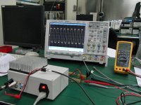
Here are some pictures of the staff I have used.
By the way, the signal distortion is already very obvious at 20KHz. If anybody interested, I will post more pictures later.
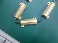
This is the load
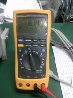
This is the DM
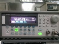
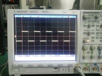
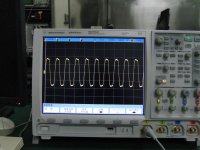
This is the signal generated and view from scope when directly feed the signal into scope channel, which show what measurement tools were used and they work perfectly.
My setup is as follows
1) two 7293 in parallel, by using standard modular application schematic as from the datasheet
2) power supply, two Agilent 30v 7.5A power supply
3) Agilent33250 signal generator
4) four 1 ohm dale resistors in serie (4.2ohm measured resistance) for load
5) Agilent MSO7054scope
Signal freq. is 1000Hz. The scope show that the output started peak-cut at about 18.6v. The max output power is merely 82w. I think this is what I can get from a IC PA? Even in that datasheet, it does not say the parallel application can output more power, it only says the parallel application can more easily drive lower impedence load. I might have got fake ICs? I really think my ICs are real.
Here are some pictures of the staff I have used.
By the way, the signal distortion is already very obvious at 20KHz. If anybody interested, I will post more pictures later.
This is the load

This is the DM

This is the signal generated and view from scope when directly feed the signal into scope channel, which show what measurement tools were used and they work perfectly.


only very good SS amps doubles power into half impedance load
or else they are designed to do so, by using lower supply voltage
so if you set it up to do 30watt into 8ohm, it might double its power to 60watt into 4ohm
no amp design pushed to its limits into 8ohm will double the power into 4ohm
or else they are designed to do so, by using lower supply voltage
so if you set it up to do 30watt into 8ohm, it might double its power to 60watt into 4ohm
no amp design pushed to its limits into 8ohm will double the power into 4ohm
It is no joke.
It is very easy to design and build an amplifier that can deliver 100W into a 4r0 resistor. That is what you see in the chipamp manufacturers' datasheets.
What they don't tell you is whether these same amplifiers can deliver real power into real 4ohm speakers that have a very significant reactance.
4r0 and 100W requires 28.28Vpk and 7.07Apk.
4ohm and 100W could require 28.28Vpk and >21Apk. There is the problem that they don't admit to !
well I bought a board on ebay a while back for fun, it featured 2 7293's in a stereo setup with power supply caps and a bridge for less that $20 US. I hooked it up to a 30-0-30 transformer and it gave me around +/- 44VDC with no load. I measured about 72 watts RMS just before clipping into an 8 ohm load (actually 7.5). So a parallel pair should deliver 100 watts plus into 4 ohms given a proper power supply(voltage and current). You need to deliver 28volts Peak or 20 volts RMS to get the 100 watts at 4 ohms. Seeing how your power supply was only +/- 30 there is very little room for losses. The data sheet shows a power output of 75 to 100 watts at 4 ohms with +/- 29 vdc(distortion 1-10%) under ideal conditions (Page 3). So your setup is within spec.
I tried to upload the data sheet but it is too big
I tried to upload the data sheet but it is too big
to get >100W @ 4 ohm, I believe you need higher voltage. According to datasheet, you need >40v.
I've a pair of TDA7293 in parallel. unfortunately the chip blew off before I can here any sound from this chip.
I've a pair of TDA7293 in parallel. unfortunately the chip blew off before I can here any sound from this chip.
Last edited:
multisync: I agree with you that my setup is within spec. But why so many still say that higher voltage may yield higher Pmax out? When we rise up the power supply voltage, we also bring up the risk. That is why we see so many 7293 blow into smoke. I have no doubt that single 7293 can output 70W+ at resonable distortion. But the parallel application, even when you follow the datasheet, cannot deliver the desired output power. Have you ever tried or wanted to try the 7293 parallel?
AndrewT: The problem is that even you follow the setup in the datasheet, you cannot get the desired result. And I have not find post in this forum which gives concrete fact that the modular application in the datasheet delivers higher power than a single 7293 delivers.
Do you mean 7293 itself is a pitfall or there are pitfalls when you use 7293?
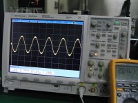
your meter shows 20.467 volts RMS
(20.467 *20.467) = 418.89
418.89/4.2 = 99.73 watts or pretty close
418/4 = 104 watts or on the money data sheet says 80-100 watts at 10% distortion with +/- 29 volts
that fuzz at the top and bottomn from the middle picture, is it ripple from your power supply?
to get a proper reading measure the power supply voltages on the chip pins, adjust the power supply if possible, and measure the output voltage on the chip pins. There will be a slight difference.
When I used to work we always measured power supply voltages on the system board pins furthest from the power supply and adjusted the power supply accordingly.
A few hundreths or tenths of a volt sometimes solved tough intermittent problems
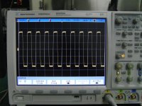
That square wave at 20khz looks like the chip is overheating and shutting down. The heatsink I used to test the stereo board was much much larger than yours and I could not drive 5 ohm loads.
AFAIK DMOS outputs require several volts extra voltage for a given output. If you are shooting for 28.8 volts peak out, you will probably need more than 30 volts for the rail voltages. Paralleling them does not increase voltage output, just current capability. So try about 35 volts for the rails and adequate heat sinking. (use 8 ohm graphs for 50 watts as guidelines. (two "50 watt 8 ohm" circuits in parallel should deliver 100 W into 4 ohms.)
your meter shows 20.467 volts RMS
(20.467 *20.467) = 418.89
418.89/4.2 = 99.73 watts or pretty close
418/4 = 104 watts or on the money data sheet says 80-100 watts at 10% distortion with +/- 29 volts
that fuzz at the top and bottomn from the middle picture, is it ripple from your power supply?
to get a proper reading measure the power supply voltages on the chip pins, adjust the power supply if possible, and measure the output voltage on the chip pins. There will be a slight difference.
When I used to work we always measured power supply voltages on the system board pins furthest from the power supply and adjusted the power supply accordingly.
A few hundreths or tenths of a volt sometimes solved tough intermittent problems
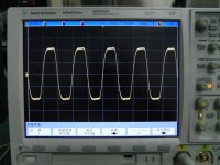
That square wave at 20khz looks like the chip is overheating and shutting down. The heatsink I used to test the stereo board was much much larger than yours and I could not drive 5 ohm loads.
Your calculation is pretty clean and clear. So the output is 99.73W with visible distortion, but bear in mind this is a dual 7293 in parallel.
That fuzz is not ripple from my power supply. I have tried both my power supply(transformer 200W at 2*27v) and Agilent power supply. They yield the same result, ie. the scope start to show distortion/peak cut at around 20v RMS.
I agree with your method of measuring power supply output. I think it is a good practice for application requiring high precission.
How can you tell from the square wave at 20khz that the chip is overheating and shutting down? If people want to know more about such skill, what is the reference that you would recommend?
Thank you for your reply!
As I mentioned in the previously, increasing power supply voltage increases the risk of overheating and blow up the chip easily. I have already see many blow their chips with supply voltage at close to the abs. max limit.AFAIK DMOS outputs require several volts extra voltage for a given output. If you are shooting for 28.8 volts peak out, you will probably need more than 30 volts for the rail voltages. Paralleling them does not increase voltage output, just current capability. So try about 35 volts for the rails and adequate heat sinking. (use 8 ohm graphs for 50 watts as guidelines. (two "50 watt 8 ohm" circuits in parallel should deliver 100 W into 4 ohms.)
I never let that amplifier under test get too hot, and take measurement at that condition. That would be unfair test condition.
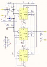
I post the schematic here. I welcome your further explaination and comments to this topic. Thank you.
Schematic, (IC2 is not installed in my implementation)
50KHz response
100KHz response
We have had this discussion many times.
In order to produce 28.2Vrms on the output the power supply must be 1.41 times or 39.762 volts, plus the voltage drop across the output transistors (usaly 2V to 5V)regardless of the load impedence.
Providing that the amp can handle the current and the transformer can supply the current, the amp should be able to produce 100watts into 4 ohms on a 30v-0-30v transformer, as only 20Vrms(56.4v p-p) wiil be required to produce 100watts into 4 ohms.
This is well under the maxium voltage rating of the transformer mentioned.
Raising the supply voltage raises the power dissipation that the transistors must expend per load current this is why it is adviseable to use a lower supply voltage when it is known that lower impedences are to be used.
I hope I am not too overly repeating things here.🙂 jer
Thanks Ger,
We should not need to repeat basic electrical equations. But many of our Members quite simply refuse to research their project. They don't want to invest the time.
They want to be spoon fed. "I want" and "you give" is the attitude.
We should not need to repeat basic electrical equations. But many of our Members quite simply refuse to research their project. They don't want to invest the time.
They want to be spoon fed. "I want" and "you give" is the attitude.
"How can you tell from the square wave at 20khz that the chip is overheating and shutting down? If people want to know more about such skill, what is the reference that you would recommend?"
As I mentioned I played around with these chips a while back and found that at low to medium frequecies the chips behaved well till they were pushed to their limits and the protection circuits started to cut in after several minutes of torture testing. At high frequencies and full power I found that the chips heated up much quicker and the protection circuits cut in nearly immediately with 5 ohm loads, at 8 ohm loads and 20khz full power about 1 minute before shutdown. I am no expert but I know that the internal temperature of the chip rises much quicker than the heatsinks and perhaps the protection cuts in to protect the chip from turning to smoke.
I believe the data sheet indicates that the required heat sinks for high power output are difficult to acchieve and recomend using "a high efficiency system is needed in those cases where the continous power exceeds 50-60 watts" an example is given in the data sheet.
We have had this discussion many times.
In order to produce 28.2Vrms on the output the power supply must be 1.41 times or 39.762 volts, plus the voltage drop across the output transistors (usaly 2V to 5V)regardless of the load impedence.
Providing that the amp can handle the current and the transformer can supply the current, the amp should be able to produce 100watts into 4 ohms on a 30v-0-30v transformer, as only 20Vrms(56.4v p-p) wiil be required to produce 100watts into 4 ohms.
This is well under the maxium voltage rating of the transformer mentioned.
Raising the supply voltage raises the power dissipation that the transistors must expend per load current this is why it is adviseable to use a lower supply voltage when it is known that lower impedences are to be used.
I hope I am not too overly repeating things here.🙂 jer
Thanks jer. But I think either you or the datasheet is wrong. I just want to know the truth. I, as many 7293 users, deserve to know the truth. People shall thank you for revealing the truth instead of blaming you for over repeating. Thank you.
single 7293 output 110w into 4ohm with +/-30V DC power supply.

multisync: thanks for your information. From my experience and your information, I feel that the chip is not a good choice for HiFi which requires power > 60w and low distortion at freq >20KHz. I will give the chip more try, based on the high efficiency application circuit in the datasheet. But I firstly need to know whether that datasheet is free of flaws. I hope people who has ever built the high efficiency application stand up and say something.
- Status
- Not open for further replies.
- Home
- Amplifiers
- Chip Amps
- Is it a joke to say pair of TDA7293 in parallel can deliver 100+W power into 4ohm

