Using a PNP transistor in a CCS, is it better to select transistors with a low Hfe ... or a high Hfe? 😕
I am currently measuring Hfe for 40 x 2AS1142s I bought recently and have observed readings ranging from 123 to 527.
Sure, a pair of transistors used for R&L channels should be matched ... but does it make any difference whether they measure 123 or 527? I can see that a different Hfe will probably change the value of the CCS resistor but is there any other effect?
Thanks,
Andy
If you're using a bipolar ccs or cascode (e.g., the diyAudio circuits or the ones in Valve Amplifiers), higher hfe is better. Note that hfe will have almost no effect on the choice of current setting resistor.
Are we supposed to guess which CCS circuit you are using?
Ah, sorry ... I had no idea there were variants. 😉
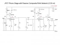
I have attached a jpg schematic, showing the way my CCSes fit into the circuit:
Thanks,
Andy
Attachments
If you're using a bipolar ccs or cascode (e.g., the diyAudio circuits or the ones in Valve Amplifiers), higher hfe is better. Note that hfe will have almost no effect on the choice of current setting resistor.
Thank you very much, SY.
Can you elucidate as to:
* why high Hfe is better, and
* how come it makes no difference to the value for the current-setting resistor (although I'm delighted to hear it! 🙂 ).
Regards,
Andy
Higher hfe means higher output resistance (what you want in a CCS). The current is determined by the reference voltage minus Vbe (0.6-0.7V) compared to the voltage dropped across the emitter resistor. Assuming that hfe is reasonably high, one can neglect base current and assume that collector and emitter current are roughly equal, and hfe doesn't enter into your calculations.
Have you thought your circuit through?
Have you thought your circuit through?
Humour me for a moment - I have never studied CCS in any detail. I can come up with an argument that lower hfe means higher output impedance.SY said:Higher hfe means higher output resistance
The emitter resistor voltage does not depend on hfe, as the resistor scales inversely with emitter current. Whether you have an xK resistor with hfe of infinity, or a 0.5xK with hfe of unity you get the same voltage and same voltage change at the emitter when the collector current changes. hfe comes in when you consider the effect of the source resistance Rb feeding the base. The CCS output resistance gets a term proportional to Rb/hfe, which argues for low hfe. Of course, in most designs people try to get a low Rb but I am not sure why (noise?).
I could call this 'back of envelope'. except that there is no envelope. There is probably a flaw in my reasoning. I assume that the Early voltage is independent of hfe.
Basically, the output resistance will be 1/hoe + Re*hfe, but the latter term usually dominates. This assumes a low source resistance at the base, which is the case for most good references.
So how does the mu (voltage gain) term for a valve turn into hfe (current gain) for a BJT? Provided Rb/hfe is sufficiently small how can base current affect the result? It is merely a tiny correction, not a scaling factor.
If hfe is reasonably large, it doesn't- Ic and Ie can be considered equal. If the source resistance to the base is high, that introduces an error into Ve ~ Vref - 0.6.
Or am I not understanding what you're saying?
Or am I not understanding what you're saying?
You said "the output resistance will be 1/hoe + Re*hfe, but the latter term usually dominates". This means that hfe directly appears as a multiplying factor, however large it is. It does not assymptotically disappear.
I have just had a look at Sedra and Smith. For the output impedance of a common base stage they give r0(1 + gm R'E) where r0 is the bare collector impedance (from the Early effect), gm is gm, and R'E is the parallel combination of RE (emitter resistor) and Rpi (base resistance). This is for high hfe. I guess Rpi increases with hfe, so can be ignored in the high hfe limit. So essentially we get r0(1+gmRE) = r0 + gmR0RE = r0 + mu RE (= ra + mu Rk in valve speak). So two different three-terminal devices (valve and BJT) essentially work in the same way, as they must - different approximations may be valid though.
Let's backtrack. r0 does not depend on hfe, but on Early voltage. gm does not depend on hfe, but on the junction temperature and current. Rpi is the only thing which depends on hfe, as Rpi = hfe/gm (I think that is right). So we have r0(1 + gm RE hfe/(gm(RE+hfe/gm))) = r0(1 + gm RE hfe/(gm RE + hfe)) which I suppose could be written as r0(1 + (gm RE)||hfe) [where x||y means xy/(x+y)].
So high hfe increases output impedance up to the point where hfe exceeds gm RE; beyond that diminishing returns set in. If we assume one diode drop across the emitter resistor then gm RE will be around thirty so we want hfe to be greater than thirty to optimise the circuit.
I'm still not clear I really understand it, but I think I understand it better than I did an hour ago!
Higher hfe comes from heavier base doping and thinner base layer. These do affect the Early voltager0 does not depend on hfe, but on Early voltage
OK, so hfe and Early voltage have (to some extent) a common source. Which way round does it work? Will higher hfe samples also tend to have higher or lower intrinsic collector resistance?
Lower. BTW, I have already noticed that the maximum voltage gain of a common emitter stage is lower for higher Hfe samples. This is contrary to a widespread belief.OK, so hfe and Early voltage have (to some extent) a common source. Which way round does it work? Will higher hfe samples also tend to have higher or lower intrinsic collector resistance?
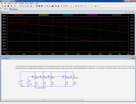
Here is the comparison with BC847's.
The quasi-static output impedance is plotted for the three hfe classes, and in addition, two synthetic classes have been added: Class mB is a A with just the Hfe brought to the B level and all other parameters unchanged, class mC is the same for the C.
The 847A has ~4.7 megohm output impedance, the class mB ~5.1 megohm and class mC 5.3 megohm: no surprise there.
But when "actual" transistors are measured, the difference is reversed, and quite dramatically: now the impedances are 2.9 and 1.9 megohm respectively:
Conclusion: the lower Hfe types are normally better for this kind of application
Attachments
Interesting. So for this type of CCS we may want hfe to be somewhat greater than 30, but not much more. Maybe somewhere around 100 would be optimal?
In theory, maybe. Problem, to find such a low Hfe in general purpose transistors, your only choice is high voltage types, with specific processes and as a result generally ugly other characteristics like high internal parasitic resistances which will ruin the benefit of the low Hfe.
transistors are cheap today - why obsess over "the best one" when two cheap Q can give order of magnitude better performance than "the best one"
cascode with base current reinjection http://www.essex.ac.uk/csee/research/audio_lab/malcolmspubdocs/J10 Enhanced cascode.pdf
or the "Baxandall Super Pair" - which we should properly credit to Boxall (try forum Google Search)
these do increase the order of the response - introduce the possibility of RF oscillation - which can be tamed with little compromise to their audio frequency performance
Last edited:
OK, let's put it another way: provided that hfe is sufficiently high (which means >> 30 for the simple CCS) and other things are not compromised, then the lower the hfe the better because that is correlated with high collector resistance. The minimum hfe would increase of the base voltage is raised and so a larger emitter resistor is used.
Yes, but a high hfe and (relatively) high emitter resistance totally overwhelm even the highest collector resistances (1/hoe, basically).
Since the term involving hfe multiplies collector resistance, rather than adding to it, hfe cannot overwhelm collector resistance.
High emitter resistance helps, provided it arises from high base voltage and not low current, as we also want high gm.
High emitter resistance helps, provided it arises from high base voltage and not low current, as we also want high gm.
- Status
- Not open for further replies.
- Home
- Design & Build
- Parts
- Is high, or low, Hfe better for a CCS?