Hello everyone!
Im designing my first pcb so as you can tell im new to designing. The type of build im designing is a pcb with 2 amps 1 audio prossesor close to what we see in car radios layout. I made it 2 sided board with few connections. So my question is about ground plane, is it necessary to use it or not and if yes how can i use it right without any coupling between connections?
Im designing my first pcb so as you can tell im new to designing. The type of build im designing is a pcb with 2 amps 1 audio prossesor close to what we see in car radios layout. I made it 2 sided board with few connections. So my question is about ground plane, is it necessary to use it or not and if yes how can i use it right without any coupling between connections?

For audio frequencies, power, and signal tracks and their return paths will either follow the traces in the ground plane or take the shortest root depending on the frequency. With DC, the return path is the path of least DC resistance (shortest distance). Above about 5 kHz, the return path follows the trace in the ground plane below. Loop areas of circuits should be minimized to prevent them from acting as antennae, both transmitting and receiving.
So, a ground plane will not solve all your problems with loop areas. It may be best to design your PCB with traces for return paths to minimize loop areas and then convert to ground plane afterwards.
Also, when combining audio and digital circuits, you want to separate the two circuits so the ground paths don't intermingle.
Lots of info on the net on this subject.
There is a thread that discusses a lot about bypass caps and their return currents, among other things. Some interesting commentary in places.
https://www.diyaudio.com/community/...pacitor-simulation-model.382329/#post-6943549
Maybe of some interest starting around: https://www.diyaudio.com/community/...apacitor-simulation-model.382329/post-6944464 ...some following posts by @KSTR may be deemed informative.
https://www.diyaudio.com/community/...pacitor-simulation-model.382329/#post-6943549
Maybe of some interest starting around: https://www.diyaudio.com/community/...apacitor-simulation-model.382329/post-6944464 ...some following posts by @KSTR may be deemed informative.

I would suggest to change the design at the schematic level before laying out a board.
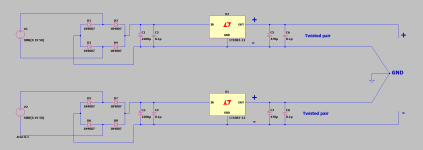
If it were me I would probably use two 7812 regulators (or maybe LT1083), each with its own transformer winding and its own separate rectifiers. Then I would use one regulator to make the + rail, and use the other regulator "upside down" to make the negative rail. The grounds would only be defined at the load. Each regulator would have its own +/- DC outputs. A separate pair of twisted wires is run from each regulator board to the load board, so there is no shared ground wire to cause "shared-impedance coupling/distortion" on the rails. IOW, its not too hard to make a better power supply system, so I would probably go with that.
If it were me I would probably use two 7812 regulators (or maybe LT1083), each with its own transformer winding and its own separate rectifiers. Then I would use one regulator to make the + rail, and use the other regulator "upside down" to make the negative rail. The grounds would only be defined at the load. Each regulator would have its own +/- DC outputs. A separate pair of twisted wires is run from each regulator board to the load board, so there is no shared ground wire to cause "shared-impedance coupling/distortion" on the rails. IOW, its not too hard to make a better power supply system, so I would probably go with that.
Last edited:
@Markw4 Thank you. Is the 7912 worse than the 7812 ? Do positive voltage regulators peform better? or just that they are the same part, so very close " characteristics " on the rails ?.
Something like this ?.
- Bruno.
Something like this ?.
- Bruno.
Attachments
Some people have reported that audio devices tend to sound better if the +/- rails have the same technical characteristics, such as output impedance versus frequency. One way to assure that is to make the regulators identical.
Also, its arguably easier to make good positive regulators than good negative ones. Moreover, not all good positive regulators have negative counterparts available.
Also, its arguably easier to make good positive regulators than good negative ones. Moreover, not all good positive regulators have negative counterparts available.
Generally positive regulators perform better, so a positive regulator that is adapted as a negative regulator will also perform better.
- Home
- Design & Build
- Electronic Design
- Is ground plane important?