I have a KEF PSW2500 powered subwoofer I'm working on. My brother gave me the 5.1 system (5 "egg" speakers + 250W sub) as payment for some work I did for him. Welp the sub wouldn't turn on. Thanks bro!
I've been over it and found it to be functional except the protection circuit wouldn't close the relay. Found a shorted transistor (Q20) in that circuit and now the sub works properly. Except for having a -0.1V offset on the output. It's been 30 years since I've done any component repairs to an amp & I'm totally unfamiliar with this type. (TBH I was never good with circuit design)
It has NO offset adjustment--or ANY other amp adjustment--on the board.
Is that "normal", "acceptable", or do I now need to find some component that has drifted off?
Welcome to diyAudio 🙂
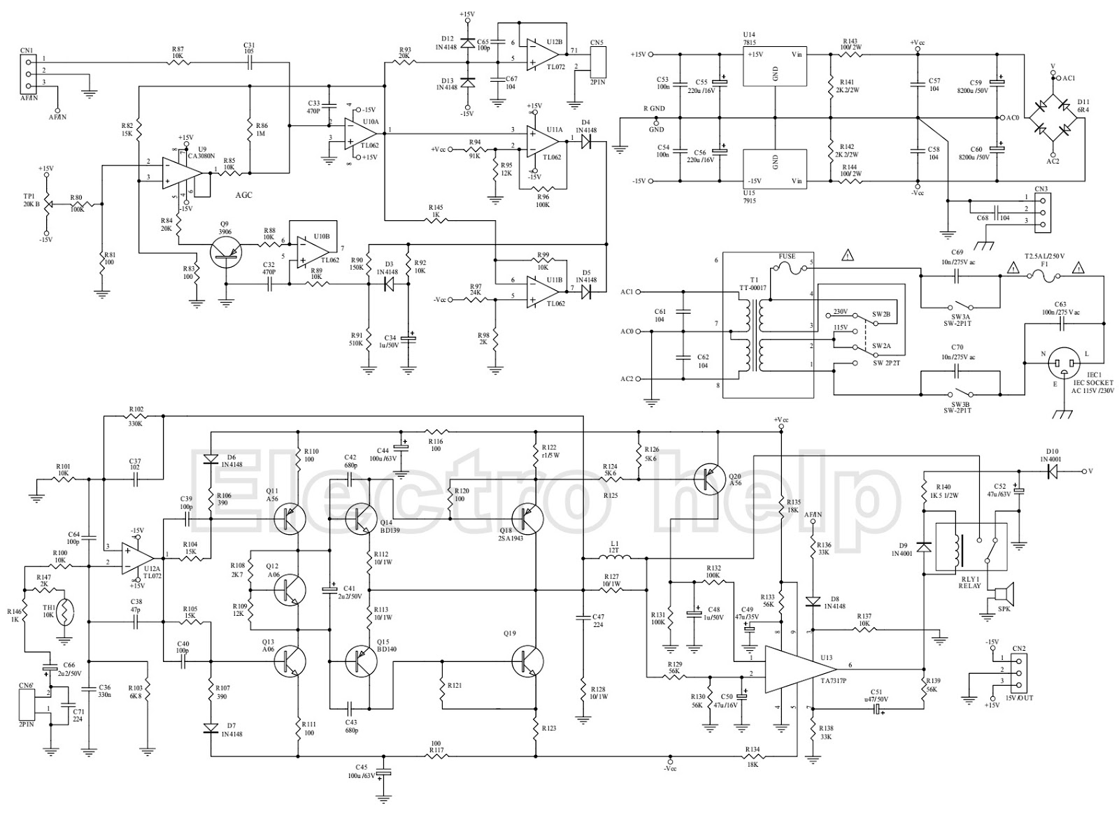
0.1 volts offset is higher than would be expected for a circuit of this type I suspect. The first thing to do is to confirm the offset by measuring the voltage on R127. That point is directly at the amplifier output. You should see the same reading (whatever that may be) on each end of the resistor. Use the correct ground when measuring.
Q20 being short sounds an odd failure mode tbh because it is basically all high impedance around that device.
I would also dangle a scope on the amp output to make sure there was no HF instability as something like that could give a skewed offset reading.
R127 is where I've been measuring, relative to circuit ground.
I agree that it's odd for Q20 to short. I DID replace U13 before I found the Q20 problem. Possibly that IC was bad--tho that's just as unlikely as Q20.
I agree that it's odd for Q20 to short. I DID replace U13 before I found the Q20 problem. Possibly that IC was bad--tho that's just as unlikely as Q20.
Has anything else been changed ? in particular U12.
If that is anything other than a TL072 (which is a FET input device) then you would expect to see an offset.
Looking closer at the circuit I see that the feedback is DC coupled (R101 is directly connected to ground) and so that means the circuit has full gain at DC. Usually that feedback resistor would be AC coupled to return the gain to unity at DC.
Taking that into account and on second thoughts it may actually be 'normal' and the offset you see is a result of the inherent 'input offset voltage' of the opamp which is in the 3 to 10mv range according to the data sheet being amplified by the high gain of the power amp stage (looks to be a gain of around 34 numerically).
Is it actually a problem though? Let's review:
100mV even into a 4ohm driver is just 2.5mW. NO thermal issue (it's a '250W' sub driver; this is 80dB below 'rated power' - though )
Into such a driver it is 25mA of VC current; if you know the driver's BL product & compliance you can calculate the driver offset from that but for most drivers, it'll be vanishingly-small. And remember - this is a Sub, not some mid driver that could contribute distortion you'd hear.
Ans: no - don't worry about it.
Last edited:
True, but if the offset were due to the amplifier oscillating like hell or due to some damaged component, then it would indicate that there is a problem even though the offset itself is small enough not to bother the loudspeaker.
However, I think Mooly's latest analysis is perfectly correct: anything below 340 mV is normal for this circuit.
However, I think Mooly's latest analysis is perfectly correct: anything below 340 mV is normal for this circuit.
Personally I´d lift one end of R101 and add a 22uF or 47uF electrolytic cap in series.
Bipolar for full orthodoxy but really a polarized one will work fine.
No matter how good the subwoofer is, I doubt it can reproduce DC, not even down to a couple Hz 🙂
And it will reduce output offset to around 10mV DC or so.
Bipolar for full orthodoxy but really a polarized one will work fine.
No matter how good the subwoofer is, I doubt it can reproduce DC, not even down to a couple Hz 🙂
And it will reduce output offset to around 10mV DC or so.
- Status
- Not open for further replies.
- Home
- Amplifiers
- Solid State
- Is 0.1V DC offset a problem?