Hello, I have a SPL CRM1200-2 and at least one of the IRFZ44n's are blown. So I am planning on replacing them all and just wondered if there is maybe a better chip to replace them with to get a few more watts out of this amp and what other modifications I would have to do like matching the outputs? I have heard it is possible to upgrade some amp's but I don't know to much about it. I would apreciate anybodys help with this.
Thanks.
Thanks.
Attachments


Unless you know an amp well, it's best to get the amp working properly with the original parts. After you 'know' that it's working properly, then you make the substitutions. It may cost a bit more but you don't have to waste time trying to determine if the replacements are the cause of the problem or if there is something else wrong with the amp.
The drive circuit on this amp 'should' be able to drive IRFZ48 FETs. They are rated for more current than the IRFZ44s.
Using a different FET will not cause the amp to make more than a few watts more (nothing audible). If the power supply FETs failed but the outputs didn't, the the Z44s may not be rugged enough. If the power supply died because the outputs failed, there's probably no reason to go to a different FET.
When you power up this amp after replacing the FETs, have them clamped tightly to the sink and have a 10 amp fuse in the B+ line.
If the outputs didn't fail, there may be another reason for the power supply failure. With the amp powered up, twist the transformer. If there are intermittantly shorted windings, the fuse will blow or you'll see sparks between the windings as you twist. You would need to find and insulate any shorted windings.
The guy I got the amp from said he had put a bigger fuse in after 1 had blown... He thought he had it under a 2 ohm load bridged after hooking the woofers up wrong.
To explain it more. I think it can only be bridged into a 4 ohm load and thats why he blew the fuse the 1st time. And then not being very smart, he put a bigger fuse in and smoked the IRFZ44N.
So should I order IRFZ48N's or go back with the IRFZ44N's? I agree with you Perry to get it working first, than modify if possible. But if it won't hurt anything to put a little stiffer FETS in then I would like to. What do you think?😕
So should I order IRFZ48N's or go back with the IRFZ44N's? I agree with you Perry to get it working first, than modify if possible. But if it won't hurt anything to put a little stiffer FETS in then I would like to. What do you think?😕
It's going to cost an additional $10 to get it working with the Z44s first then change them to Z48s. I think it's well worth the expense. The Z44s will not be damaged and can be used for other repairs if you'd like.
If I'm not mistaken, this amp has a regulated power supply and unless you have a 12v DC power supply with variable voltage and an amp meter, it may be difficult to tell if the drive circuit is able to turn the FETs off quickly enough at the maximum duty cycle. I think it will be OK with Z48s but I've never tried them in one of these.
Check the output transistors before you order parts. If you find any that read anything near 0 ohms between legs 2 and 3, pull them from the board and check them.
Before you replace the transistors, clean all of the black soot from the board. I'd suggest using acetone and a toothbrush. Don't use a transparent toothbrush. Acetone melts them. Do this outdoors. Read the label on the acetone if you've never used it.
I will get both z44's and z48's. I checked all of the bigger output transistor's but I didn't test the smaller ones in between the z44's and the bigger outputs. Which I think are diodes (FMG222) and (TIP41C),(TIP42C).
All the output trans. were open between leg 2 and 3. Can you explain the maximum duty cycle shutting down the FET's? How can you tell if It has a regulated power supply? Is that the same as a PWM? I did post some pic's above of the multipin controller chips, also there was a white 4 pin chip next to them. Those control the power supply right?
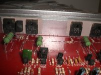
I have a Yellow top Optima battery with inline fuse holder, But no way to make variable voltage. I do have several amp meters and 8 DMM's which 2 are Fluke's. I don't have Osciliscope, but am in the market for one. So do I need to buy a variable power supply? And yes to your question, No Q45. I think they use this same board for their higher wattage amp's, It look's like more Fet's could be added. (Empty slots). Anyway would you suggest I order any other parts to replace? like I see a couple of resistors that look like they have been hot. It's the small resistors in front of the Z44's. And any parts to upgrade after getting amp working? Thanks.
All the output trans. were open between leg 2 and 3. Can you explain the maximum duty cycle shutting down the FET's? How can you tell if It has a regulated power supply? Is that the same as a PWM? I did post some pic's above of the multipin controller chips, also there was a white 4 pin chip next to them. Those control the power supply right?
I have a Yellow top Optima battery with inline fuse holder, But no way to make variable voltage. I do have several amp meters and 8 DMM's which 2 are Fluke's. I don't have Osciliscope, but am in the market for one. So do I need to buy a variable power supply? And yes to your question, No Q45. I think they use this same board for their higher wattage amp's, It look's like more Fet's could be added. (Empty slots). Anyway would you suggest I order any other parts to replace? like I see a couple of resistors that look like they have been hot. It's the small resistors in front of the Z44's. And any parts to upgrade after getting amp working? Thanks.
I will get both z44's and z48's. I checked all of the bigger output transistor's but I didn't test the smaller ones in between the z44's and the bigger outputs. Which I think are diodes (FMG222) and (TIP41C),(TIP42C).
**** The FMG22S and FMG22R are the rectifiers. They rarely fail. The TIP41 and 42 are part of the ±15v regulators.
Can you explain the maximum duty cycle shutting down the FET's?
**** Regulated power supplies vary the width of the pulse to regulate to rail voltage. When the target rail voltage is reached, the 'on' time of the pulse is reduced. This produces more dead time between pulses. In each power supply, there are 2 banks of FETs. If these two banks are ever on at the same time, the FETs run VERY hot or go up in smoke. The drive circuit is responsible for turning the FETs on/off. When there is a short on time, there is a longer off time. With a long dead time, if the drivers turn the FETs off relatively slowly, it's not significant because they have plenty of time before the other bank will switch on. At the maximum duty cycle, the driver transistors have to turn the FETs off very quickly because there is very little dead time. The Z48s are more difficult to switch on an off so if the drive circuit is relatively weak, the two banks of FETs could possibly be on at the same time. To determine if the FETs are being switched off quickly enough, you must force the supply to drive the FETs with the maximum pulse width. The easiest way to do this is to lower the voltage on the supply. This forces the pulse width to increase. If you see the current increase as the voltage is reduced, the FETs are not switching off quickly enough. Page 85 of my site has more information.
How can you tell if It has a regulated power supply?
**** Part of the rail voltage is being driven back into the error amp of the IC. For unregulated amps, you won't have this feedback.
Is that the same as a PWM?
**** Yes.
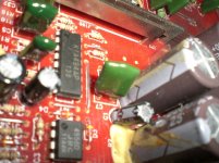
I did post some pic's above of the multipin controller chips, also there was a white 4 pin chip next to them. Those control the power supply right?
**** The TLx94 controls the power supply. The white IC is an opto-coupler and is generally used in the muting circuit in these amps.
So do I need to buy a variable power supply?
**** Only if you intend to continue doing this type of work.
And yes to your question, No Q45.
**** This is the same as one of the power acoustic 1200 watt amps.
Anyway would you suggest I order any other parts to replace? like I see a couple of resistors that look like they have been hot. It's the small resistors in front of the Z44's
**** Yes. The 100 ohm gate resistors often fail. You should check them after you remove the FETs. If you decide to use the Z48s, you may want to change these to 68 or 47 ohm resistors. Sometimes the 2SA1266 (KTA1266) drivers fail.
And any parts to upgrade after getting amp working?
**** Not really. When you 'upgrade' parts, it doesn't always work out as you'd expect. Until you get some experience, you should be satisfied with getting the amp working.
**** The FMG22S and FMG22R are the rectifiers. They rarely fail. The TIP41 and 42 are part of the ±15v regulators.
Can you explain the maximum duty cycle shutting down the FET's?
**** Regulated power supplies vary the width of the pulse to regulate to rail voltage. When the target rail voltage is reached, the 'on' time of the pulse is reduced. This produces more dead time between pulses. In each power supply, there are 2 banks of FETs. If these two banks are ever on at the same time, the FETs run VERY hot or go up in smoke. The drive circuit is responsible for turning the FETs on/off. When there is a short on time, there is a longer off time. With a long dead time, if the drivers turn the FETs off relatively slowly, it's not significant because they have plenty of time before the other bank will switch on. At the maximum duty cycle, the driver transistors have to turn the FETs off very quickly because there is very little dead time. The Z48s are more difficult to switch on an off so if the drive circuit is relatively weak, the two banks of FETs could possibly be on at the same time. To determine if the FETs are being switched off quickly enough, you must force the supply to drive the FETs with the maximum pulse width. The easiest way to do this is to lower the voltage on the supply. This forces the pulse width to increase. If you see the current increase as the voltage is reduced, the FETs are not switching off quickly enough. Page 85 of my site has more information.
How can you tell if It has a regulated power supply?
**** Part of the rail voltage is being driven back into the error amp of the IC. For unregulated amps, you won't have this feedback.
Is that the same as a PWM?
**** Yes.
I did post some pic's above of the multipin controller chips, also there was a white 4 pin chip next to them. Those control the power supply right?
**** The TLx94 controls the power supply. The white IC is an opto-coupler and is generally used in the muting circuit in these amps.
So do I need to buy a variable power supply?
**** Only if you intend to continue doing this type of work.
And yes to your question, No Q45.
**** This is the same as one of the power acoustic 1200 watt amps.
Anyway would you suggest I order any other parts to replace? like I see a couple of resistors that look like they have been hot. It's the small resistors in front of the Z44's
**** Yes. The 100 ohm gate resistors often fail. You should check them after you remove the FETs. If you decide to use the Z48s, you may want to change these to 68 or 47 ohm resistors. Sometimes the 2SA1266 (KTA1266) drivers fail.
And any parts to upgrade after getting amp working?
**** Not really. When you 'upgrade' parts, it doesn't always work out as you'd expect. Until you get some experience, you should be satisfied with getting the amp working.
Yes it is a Power Acoustik design. Yep you are right I will worry less about modifications and just get it going.
Also, is there one gate resistor per IRFZ44n fet? And do I have to remove the resistor to get correct reading on them? Or can I just remove the fet's and test the gate resistors? I tried testing them in place and I am getting 46 at one and then 202 at the one next it. Only 2-3 of them were 100 ohm?
Also, is there one gate resistor per IRFZ44n fet? And do I have to remove the resistor to get correct reading on them? Or can I just remove the fet's and test the gate resistors? I tried testing them in place and I am getting 46 at one and then 202 at the one next it. Only 2-3 of them were 100 ohm?
- Status
- Not open for further replies.
- Home
- General Interest
- Car Audio
- IRFZ44N Chip Question?