Hi all experts and good people !
I have built Holtons scaleable mosfet amp with the good(?) old 2sj55 /2sk175 and it works just great. I am using +-40v. rail supply. Now I wonder if it´s possible to use IRF540 / 9540 instead of the Hitachi mosfet. If it is possible, do I have to change something or, does anyone have a schematic with this output transistors ?
Regards,
Bengt
This subject has come up before in the forum. I suggest you
use the search feature to look for it. In my own opinion, the
probable issue is that the bias voltages will be different and
you might want to consider the resistance in series with the
Sources of the devices for better thermal stability.
use the search feature to look for it. In my own opinion, the
probable issue is that the bias voltages will be different and
you might want to consider the resistance in series with the
Sources of the devices for better thermal stability.
I have tried to search the forum but I did not find exactly what I wanted about this. Anyway, I tested to change to this IRF instead and the problem seems to be that I can not bias up the transistors, whit great distorsion on low volume. When I increase the input they draw current and on higher volume they sounds better. Any sugestions ?
Bengt
Bengt
The Hitachi lateral mosfets have a low transconductance and a low threshold voltage. They are much easier to use in linear applications than the high gm and high threshold conventional power mosfets like the IRF540.
You can make good amps with 540/9540 and similar devices, but the simple biasing used with lateral fets isn't adequate for conventional devices.
In most other respects the lateral mosfets are crude, old-technology parts, and for switching applications more modern device structures have replaced them. It's just that for linear amplifiers, where a very low RDSon isn't needed, then lateral mosfets are still better devices for the job.
So, I changed the bias circuit, using a BD139 that I put on the heatsink to prevent thermal runaway and it seems to work very well.
But now I have another (stupid probably) question. Wich way is the best to connect the IRF transistors, the Source driving the speakers or the drain ? I have looked at different schematics where some has the Sourse driving the speakers and nearly the same construktion but swapped N and P channel to let the Drain drive the speaker. Can anyone please explain for me ?
Cheers !!!
Bengt
There are a bunch of topologies out there. Generally, you
are talking about two of the three operating modes - Common
Drain, where the Source is connected to the output, and Common
Source, where the Drain is connected to the output.
Common Drain is used for followers, and they are very linear.
Common Source gives you voltage gain as well as current gain,
and this has its uses also.
Both are effective uses, and are sometimes combined, as in
quasi-complementary output stages.
In any case, it all depends on everything else.....
I'd leave your design alone. The threshold voltages of the vertical mosfet devices are much higher so you would have to bias them up, and that ends up subtracting from your voltage swing so the power output goes down. The amp would probably sound the same but have less output.
A second consideration is that the tempco of the IRF devices is positive for small currents, unlike the Hitachi laterals at small current. So the output stage would tend to increase bias current as temperature rose, and you would have to counteract that with a current sense on the outputs or some temperature compensation scheme. The lateral devices are much more appropriate for this type of audio amp design for that reason alone.
I actually did what you're saying to an old Dynaco 400 about 6 years ago. Here there is a benefit, since you don't have to cascode the output stage for second breakdown prevention (the wasted swing due to cascoding was about equal to the wasted swing due to higher bias voltage). I think I had about 4-5 volts of bias, and tried to track temperature with the Vbe multiplier on the heatsink. I used a TO-3 packaged device, the IRF130 and 9130 as I recall, to make the switch easy. I had numerous problems specific to mosfets, such as a high-frequency parasitic oscillation due to the lack of proper series resistances in each gate drive. Once I got the bugs worked out, it was and is a good high powered amp. Overall the output stage was much simpler than the original, and far more rugged. A good use for old iron.....
Thanks for your reply!
I am not an expert in this area but I am very intrested and want to learn "everything" to make constructions. What I did is this:
I have the Scaleable amp from Holtons site that I made with Hitachi K175/J55 that I had from "back in time". The amp works just great, with no problems and a great sound ( I took it to the lokal HIFI store and they where impressed of the sound.... hmmm).
Then I wanted to see if this could work with the IRF HEXFET instead, mostly because of the price difference and that the Hitachi is old and so on. So, instead of a simple pot between the Gates to bias (this did not work good) I putted a BD139 and 2 resistors paralelt with the pot to increase the bias ro the IRF and, to make a thermal connection to the IRF so the BD139 would prevent thermal runnaway. I would like to show the schematic here BUT, because the half construktion is Holtons, I think I can not.
So, the amp runs good, without any thermal runnaway but the sound from it is not the same as with the Hitachi MOSFET, they give a smooth and warm sound and the IRF gives a hard and...... difficult to explain really. I think that I have to do some changes in the circuit to get "better sound" but I have not figured out what to do yet. just continue working......
Regards !
Bengt
Good for you!
I think you could safely post the output stage and bias, since
that is not Holton's.
Probably more bias is called for on the sound issue, and usually
fewer devices is appropriate, but the heat issue might not
allow for this in your amp.
Also, you don't mention Source resistor values, and you'll
definitely need some, say at least .47 ohms.
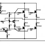
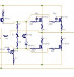
Here is the output stage. I putted 0.27 ohm as source resistors and I biased up to approx 150 mA on each rail with +-35 volt. Before I did not put the BD139 on the heatsink , I could see that it had some thermal runnaway because the amp was increasing within the heat of the IRF but when I putted the BD139 together with the IRF it seems to be stable and decrease the bias when the heatsink gets warm.
Bengt
Bengt
Attachments
bengt said:Before I did not put the BD139 on the heatsink , I could see that it had some thermal runnaway because the amp was increasing within the heat of the IRF
I usually allow for quite a bit of drift in either direction, say as
much as 25% while the amp is warming up. The primary thing
is that it stays stable once it reaches its ordinary operating
temperature. This usually takes an hour or so, but you can
tell because the temperature stops changing at that point.
This is easier to say with high bias amplifiers, as they tend to
have a more constant sink temperature after an hour or so and
that temperature is less dependent on the signal and load.
hmmm.......
Why does my picture not appear on the site ? I can se them when I preview the post....🙁
Why does my picture not appear on the site ? I can se them when I preview the post....🙁
Hv u tested the amp? If ok then how about giving all details like full circuit diagram along with layout of PCB.
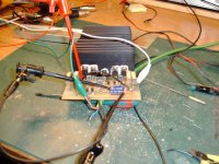
I am testing the amp with a PCB that is not "made" for it. I am still under construction of the PCB and testing the amplifier. But if you are intressted I will ofcorse share my "ideas" with you.
So, I am wondering if I need a small capasitator between Gate/Drain on the N-channel mosfet and if, what value. On the original it's 68pF but checking old elektor constructions they use two, Gate/Sourse 330pf and Gate/Drain 33pf. This last I tried without any success. The amp just putted strange sounds out. So, any suggestions ?
/Bengt
- Status
- Not open for further replies.
- Home
- Amplifiers
- Solid State
- Irf540/9540