I have a problem with my diy smps for class D. Sometimes a transistor explodes when turned ON. Unfortunately, it also takes circuit 2153 with it. Apparently missing soft start circuit. Runs absolutely reliably when it survives the start.
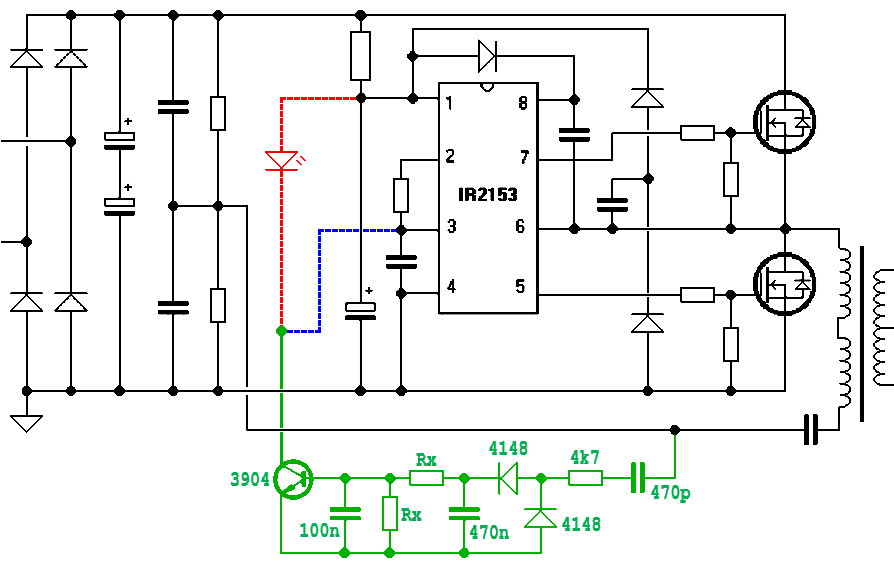
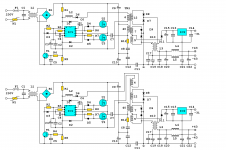
I need to implement a soft start circuit. I found two similar schematics. Version 1 - via LED to pin1 (Red line in schematic). Version 2 - to pin3 (Blue line in schematic) Please advise me. Which is better?
Thank You.
I need to implement a soft start circuit. I found two similar schematics. Version 1 - via LED to pin1 (Red line in schematic). Version 2 - to pin3 (Blue line in schematic) Please advise me. Which is better?
Thank You.
Attachments

What you need is an NTC inrush limiter, it slows everything down.
Mind you, only by fractions of a second, but that´s enough.
Mind you, only by fractions of a second, but that´s enough.
NTC inrush and resistor with delayed relay bypass can also do the trick if you want to avoid the ntc ******* the power the whole time. You can also use a more advanced soft start circuit that uses a triac to slowly ramp up power to slowly charge those caps
Could you be getting shoot-through? Do you need to decrease the resistance of the gate-source resistors to ensure the transistors stay off during start up? Also, adding a diode (1N4148) in parallel with the gate resistors to the IR2153 to discharge them more quickly may help prevent shoot-through. What is the oscillator frequency? Is the capacitor in series with the transformer primary large enough so that the resonance frequency of the leakage inductance of the transformer / capacitor combination is sufficiently below the switching speed as to maintain ZVS when starting up? If the frequency of oscillation is equal to the resonant frequency, the series resonance will drop the impedance nearly to zero with a corresponding short circuit.
When I was experimenting with this stuff, I use gate drive transformers to make it so that I would be less likely to blow the control circuitry. I wrote a guide a while back on making SMPS that might be useful to you:
Building a SMPS.pdf - Google Drive
When I was experimenting with this stuff, I use gate drive transformers to make it so that I would be less likely to blow the control circuitry. I wrote a guide a while back on making SMPS that might be useful to you:
Building a SMPS.pdf - Google Drive
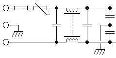
HOW would we know? 😕But 230VAC input section already include 18ohm 4A NTC.
You chopped that section off. 🙄
In your circuit neither. The 470p capacitor is connected to the soft centre of the reservoir capacitors which is a 'stiff' voltage. The circuit operates on the dV/dT (=I/C) across the 470p capacitor as an indicator of current. Connect the 470p capacitor to the other side of the resonant capacitor. As an aside note that the circuit, correctly, only senses when the upper mosfet is on charging the resonant tank. The bottom mosfet effectively just recycles the resonant current. The signal filtering to the 3904 might be too aggressive. Try smaller Cs. Use version 2) to shut it down. Version 1) just lights the LED but you already know the supply has blown up as a result of the bright blue flash and massive bang!
I think it has something to do with the startup/UVLO of the chip, as the damage due to a high inrush current usually pertains to the input rectifier.
You wouldn't face any of these issues if you use an emitter follower from the input DC to supply the 2153 auxiliary Vcc and turn that off (using diode summing) as soon as the transformer aux winding is energised. This may not be as simple as what you've drawn but is definitely more robust.
You wouldn't face any of these issues if you use an emitter follower from the input DC to supply the 2153 auxiliary Vcc and turn that off (using diode summing) as soon as the transformer aux winding is energised. This may not be as simple as what you've drawn but is definitely more robust.
Last edited:
What is Cs?
Sorry. C's, capacitors. I was kind of wrong about Version 1) it should/might disable the IC by removing its power as supplied from the HT dropper resistor.
Attachments
Last edited:
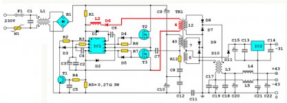
steppler said:What is the meaning of the red marked part of the circuit?
Once the IC has started up, the voltage from the red winding is supposed to run the IC thereafter. A variation of this method (picture) also cuts off the starting power supply by reverse biasing the left-side diode after startup, by using a slightly higher voltage on the auxiliary winding.

- Home
- Amplifiers
- Power Supplies
- IR2153 Soft Start