I would like to build an inverter from +12VDC to 220VAC.. Should i follow the schematic of a typical SMPS in wich i replace a ferrite transformer with an iron transformer and without the capacitor at the output or do i need a special schematic? Thanx in advance to all! 🙂
Give me a little time on that one. I would like to know what drawing software people are using to post neat schematics here? I have my schematics in Pspice capture. I have to do some converting to post them. Someone got a freeware that converts Pspice capture directly to jpg, gif, etc.
The reason, I ask about power; low power from 12VDC is not too difficult. High power should be from something like four 12VDC batteries in series or 48VDC. Use enough batteries in series and you can skip the DC to DC conversion from 12 VDC to 325 VDC and use just a Class D.
The reason, I ask about power; low power from 12VDC is not too difficult. High power should be from something like four 12VDC batteries in series or 48VDC. Use enough batteries in series and you can skip the DC to DC conversion from 12 VDC to 325 VDC and use just a Class D.
Hello,
LTspice has a screen to bitmap converter when a schematic window is open. After you copy it, then you can go to Windows Paint and under the edit tab choose paste. Then you can resave it as GIF or JPEP. Once you save it in those formats, you need to repaste a bitmap version back to the Paint screen to resave it in another format if so desired. If you don't, each time you resave it the image loses quality.
LTspice has a screen to bitmap converter when a schematic window is open. After you copy it, then you can go to Windows Paint and under the edit tab choose paste. Then you can resave it as GIF or JPEP. Once you save it in those formats, you need to repaste a bitmap version back to the Paint screen to resave it in another format if so desired. If you don't, each time you resave it the image loses quality.
mwh-eng said:(...)Someone got a freeware that converts Pspice capture directly to jpg, gif, etc.(...)
I just found WinGrab at http://www.brothersoft.com/soft/iwg15009.exe . It can do screen capture, cropping the image and saving as JPG or PNG. Its UI is confusing and the help is pretty useless, but after a few minutes of stumbling around with it I was able to save a nice cropped image of a PSpice Capture window. A nifty freeware graphics viewer is IrfanView at http://www.irfanview.com
The class-D approximation is valid but has great complexity and most applications doesn't require a sinewave to work properly. Most consumer 12V DC to 220V AC converters use a coherent square wave to approximate a sine wave. Even DC may be right for somme applications like light bulbs, resistive loads, SMPS-powered equipment and other applications that rectify mains before using it
In standard consumer inverters, the 12V DC supply is elevated to about 320V DC unregulated using a simple transformer coupled push-pull circuit switching at about 40Khz. These 320V DC are switched over the load using a phase controlled full bridge whose output passes through common mode and a differential mode filters
The duty cycle of the square wave is regulated in a way such that the RMS value of the output waveform equals 230V even though the peak value is proportional to the voltage present on the 12V line and subject to fluctuations
The switching frequency of the full bridge is factory set to 50Hz or 60Hz depending on the country by means of a trimmer. The control circuit of the phase shifted full bridge appears to be very simple since it uses only a NE556 dual timer and a CD4013 dual CMOS flip-flop
The full bridge uses MOSFETs as switching devices and gate driving tends to be very rudimentary
Thanks Andy!!!!!!!
I will try your instructions. I have been using Irfanview for a few years and that is a great freeware.
I will try your instructions. I have been using Irfanview for a few years and that is a great freeware.
I wonder if Europe has the equivalent of a Wal-Mart. They sell a 200 W inverter for about $35.00 last time I looked a few years ago. Of course it converts 12VDC to 120 Vrms, I think.
Driving to a store and buying one is NOT a DIY method and not recommended, unless you want to take one apart and reverse engineer it for educational purposes.
Most of the less expensive inverters use a modified sinewave or modified rectangular waveform that has the same effective voltage of a sinewave. They will work fine for many applications. I built a 12VDC to adjustable 90 to 120 VDC converter for running a weedeater from my truck battery. Be careful with running some devices from DC such as variable speed drills, as it smokes the control circuit. Also do the conversions from peak to average, for effective voltages, if the device can handle the DC.
MaXiZ
This is my first attempt to post a graphic from Pspice. Used Microsoft Word and Irfanview. Have not figured out WinGrab yet.
You didn't say many specifics about your application, yet.
This is my first attempt to post a graphic from Pspice. Used Microsoft Word and Irfanview. Have not figured out WinGrab yet.
You didn't say many specifics about your application, yet.
You're welcome mwh-eng. I hope it clicks for you and you can get the copying and pasting to work.
I need this inverter for a neon.. From +12V DC to 220V AC@50hz i think..
Some schematic? Some hint for this? Thanx again to all.
Some schematic? Some hint for this? Thanx again to all.
ar...a neon...how big izzit?? and u didn't mention ur current needs...if u are running something like a NE-2 or maybe a nixie tube...a MAX1771 will do nicely...but I guess u're gonna use a neon tube...then we have to look at higher currents and of course it has to be AC...or else one side will not light...high frequency will be preferred as it will cause less "flicker"
So a typical push-pull SMPS schematic without the capacitor to have +/- at the end is enough? Since u've said that i need high frequency.. right? Wrong?? Thanx in advance
it would really depends on what tube u're trying to run...if it's a neon requiring a few kV of EMF then u need a different design...
Are you sure that is a neon..????
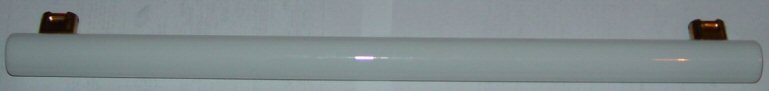
Last time I saw a light tube like that, with similar sockets, it was called a "Linestra" tube, made by either Osram or Philips.
That kind of tube was a "glow lamp" type in neon tube disguise.
You would still need 220V to drive it though......
Last time I saw a light tube like that, with similar sockets, it was called a "Linestra" tube, made by either Osram or Philips.
That kind of tube was a "glow lamp" type in neon tube disguise.
You would still need 220V to drive it though......
- Status
- Not open for further replies.
- Home
- Amplifiers
- Solid State
- Inverter