Hi everyone.
I've come across the inverted triode configuration a couple of times, also on diyaudio, and most times the benefit that the designers claim is the low output impedance, which basically is close to 1/gm. The price to pay is a voltage gain which is a fraction of one.
But 1/g happends to be the output impedance of a cathode follower too, which delivers a higher gain, with great input impedance figure and much higher anode dissipation (versus grid dissipation on the inverted configuration).
This leads me to think that I'm missing something here...
What is the benefit of an inverted configuration compared to a follower topology?
Thanks!
Draw a napkin-diagram, and post. label it well, so that all following commenters can reference particular “parts of the diagram” clearly and effectively. You'll get a lot of interesting replies, this way. ⋅-=≡ GoatGuy ✓ ≡=-⋅
Common in and out element:
Connect the cathode "as" if it is a cathode.
Control in element:
Connect the plate to the signal voltage input "as" if it is a grid (has an extremely low u).
Output element:
Connect the grid "as" if it is a Plate (to the plate load resistor).
What do you get:
Very low voltage gain (far less than unity), and very low power output.
The grid becomes a very low voltage, very low current "plate"
If you try and get higher power output, what do you get . . .
You get burned out grid wires, they can not "take the heat".
Just how I see it.
Last edited:
.... inverted triode configuration ...output impedance, which basically is close to 1/gm. ...
I think it is 1/gm divided by Mu.
So a 6080, cathode follower about 100 Ohms, inverted potentially about 38 Ohms.
The real issue is, as sir 6A3 says, that the grid will NOT take nearly as much current as the plate-cathode path. And low current is low Gm. Unless the tube is specially made to work inverted, it won't be a lot better in Inverted.
The only made-for-Inverted tube I ever saw was a LOW current HIGH voltage bottle made for monitoring high voltage low current sources.
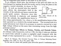
The gain is ~1/Mu. Steve Bench did quite a bit with this. One cct used several triodes (5687s ?) in parallel. First mentioned in Terman's text circa 1930.
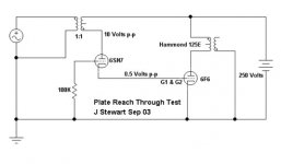
One real application is the measurement of very high voltages, using a specially constructed tube, the anode connexion brought out thru the top. The load at the test point is negligible.
For a project some time back I measured the influence of changing plate voltage on the cathode, it closely followed 1/MU. That on one triode of a 6SN7.
Or are you referring to John Broskie's Inverted Triode?😀
Attachments
I think it is 1/gm divided by Mu.
So a 6080, cathode follower about 100 Ohms, inverted potentially about 38 Ohms.
That would make sense, but it doesn't seem to be the case. See, here: Inverted Tube Operation
"[...] the "new" plate resistance is always approximately equal to 1/gm(not inverted gm). Thus, you can "predict" the plate resistance in inverted operation. A tube with a gm of 10 mS, for instance, will have a plate resistance of about 100 ohms."
Now, here is the trick:
He uses 10 parallel 5687 tubes, and 700 mA quiescent current. That is, 70 mA per tube, which seems overkill (this current flows into the grid! The dataseet states a max DC grid current of just 6 mA. And the highest of the typical operating conditions recommend about 35 mA plate current, which is half!).
But this setup is feasable because of the low grid-cathode voltage. As the grid is the effective plate, a much higher current is allowed before power dissipation is an issue.

At 70 mA idle current, gm is higher than it would be in a cathode follower. (Aproximately double). Thus you can get about half the output impedance.
This looks like too much of a hassle, but at least if makes sense...
Steve Bench Paper on The Inverted Triode
Here is the link so that others can follow this thread-
Inverted Tube Operation
And Terman's reference to the Inverted Triode attached.
Here is the link so that others can follow this thread-
Inverted Tube Operation
And Terman's reference to the Inverted Triode attached.
Attachments
- Home
- Amplifiers
- Tubes / Valves
- Inverted triode vs. regular follower