ChipAmp in CNC milled billet aluminum chassis? Yeah!
ChipAmp in CNC milled billet aluminum chassis? Yeah!
Hello all,
I'm Peter, 25 years old, living with my girlfriend in the Netherlands, working as a CNC machinist (3 and 4 axis machines, programming done by me and my colleagues using cad/cam. I've been programming old school style before for a few years), extremely interested in everything that's technical and i'm an extreme perfectionist in everything that i make or do.

About ten years ago I've build a Gainclone, his project was done with my brother (who's also a member of this forum).
I've been using it on and off since then. The main reason for not using it a lot is because it's not really user friendly.
It had only one channel, a simple (cracking and cheap) pot for volume control and no on and off switch.
You might say that this is the Gainclone in it's purest form, which it is. But i'm more demanding, i don't want to walk up to my amp all the time to change volume, pull the plugs and insert others to change the input.
So i decided to take it all apart and give it a make over
But i'd like to do this project publicly so others can benefit.
Most of things i can do myself, but i must say that i practically have no experience or knowledge about electronics. The things i do is basically common sense for me.
But i could really use some help every now and then
If anyone has any comments or questions, please comment or ask!
Thanks in advance for any replies!
Regards,
Peter
P.s. i hope my English is o.k. I've done my best to type as understandable as possible

ChipAmp in CNC milled billet aluminum chassis? Yeah!
Hello all,
I'm Peter, 25 years old, living with my girlfriend in the Netherlands, working as a CNC machinist (3 and 4 axis machines, programming done by me and my colleagues using cad/cam. I've been programming old school style before for a few years), extremely interested in everything that's technical and i'm an extreme perfectionist in everything that i make or do.
About ten years ago I've build a Gainclone, his project was done with my brother (who's also a member of this forum).
I've been using it on and off since then. The main reason for not using it a lot is because it's not really user friendly.
It had only one channel, a simple (cracking and cheap) pot for volume control and no on and off switch.
You might say that this is the Gainclone in it's purest form, which it is. But i'm more demanding, i don't want to walk up to my amp all the time to change volume, pull the plugs and insert others to change the input.
So i decided to take it all apart and give it a make over
But i'd like to do this project publicly so others can benefit.
Most of things i can do myself, but i must say that i practically have no experience or knowledge about electronics. The things i do is basically common sense for me.
But i could really use some help every now and then
If anyone has any comments or questions, please comment or ask!
Thanks in advance for any replies!
Regards,
Peter
P.s. i hope my English is o.k. I've done my best to type as understandable as possible
Last edited:
Welcome to diyAudio Peter 🙂
That sounds quite an ambitious project... I'd perhaps suggest breaking it down and posting the relevant questions to the appropriate forums. You'll get the best and most responses that way.
That sounds quite an ambitious project... I'd perhaps suggest breaking it down and posting the relevant questions to the appropriate forums. You'll get the best and most responses that way.
Hi Mooly,
That's a quick reply!
I see you're a moderator, any idea why i can't post pic's?
Thanks.
- peter
That's a quick reply!
I see you're a moderator, any idea why i can't post pic's?
Thanks.
- peter
You should be able to post OK. This is the standard procedure,
To add a photo, files or non standard files.
First click "go advanced" in the box below the "quick reply" message box. Doesn't matter if you decide half way through a message to do that, it carries it forward.
Then click "Manage attachements". Maximise the new Window so that you can see all the text.
Click browse in the first box at the top and find your picture. Repeat for any more pictures.
Click upload... a message appears "uploading"
When complete the files will show as being attached. Now click the small text that says "close this window"
The pictures should now be attached and when you submit your post they will appear.
Make sure your pics aren't too big, a couple of 100k is plenty, and many members object when they are massive and it alters the margins
It tells you in the attachments window what max sizes are allowed.
If you want to attach a file that has a non standard format for example excel, circuit simulation etc then try putting the files in a zipped folder and attaching that.
First update
I haven't really posted anything since I've started this thread,
But i think it's time to start posting some things here🙂
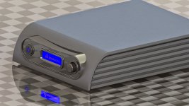
I've included a basic idea of what i'd like to make
The amplifier will be milled out of solid aluminum and anodized.
I'm not sure whether it's going to be black or clear, I really like both.
I'll fit front and back panels into the case, they'll be made of polished stainless.
I haven't really posted anything since I've started this thread,
But i think it's time to start posting some things here🙂
I've included a basic idea of what i'd like to make
The amplifier will be milled out of solid aluminum and anodized.
I'm not sure whether it's going to be black or clear, I really like both.
I'll fit front and back panels into the case, they'll be made of polished stainless.
Attachments
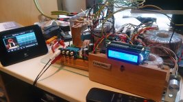

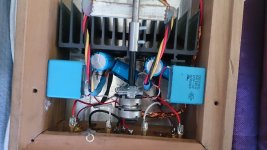
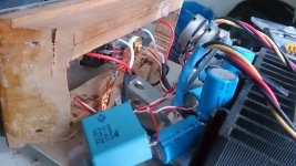
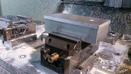
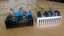
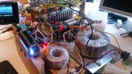
I started to tweak this amplifier which was initially build about ten years ago.
It was just very very basic, two LM3875 IC's and a 20K pot.
No capacitors after the bridge rectifier, no filters, no zobel network, no snubbers, no star-ground, no remote, no channels to choose from nothing, no bass 🙄 ...
The pictures included in this post will show what the amp was a few months ago
Of course there used to be an aluminum cover on it.
Attachments

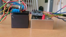
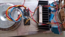
The main reason for me to change this amplifier was basically because the old pot was cracking pretty loud.
At first i just wanted to replace the pot.
But... It might be familiar for some, there's no end to a project..
At first i just wanted to replace the pot.
But... It might be familiar for some, there's no end to a project..
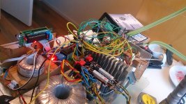
This was basically the first step i took:
get the pre-amp board instead of the volume pot.
But it was still buzzing pretty badly, lots of noise and ground issues.
And of course a pretty bad hum caused by the fact that there was no filter after the bridge rectifiers.
get the pre-amp board instead of the volume pot.
But it was still buzzing pretty badly, lots of noise and ground issues.
And of course a pretty bad hum caused by the fact that there was no filter after the bridge rectifiers.
Attachments

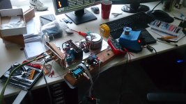
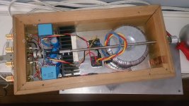
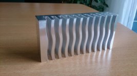
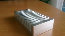
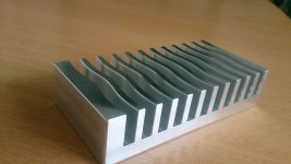
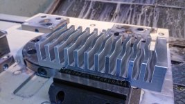
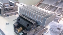
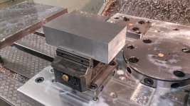
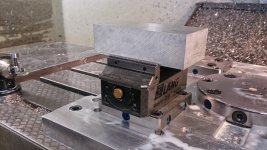
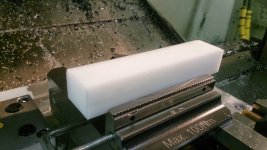
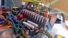
I decided i wanted to try the LM3886 over the LM3875.
Only to find out that it didn't fit on my old heatsink.
Therefore, i had to make one.
Why buy it if you can make it?
Only to find out that it didn't fit on my old heatsink.
Therefore, i had to make one.
Why buy it if you can make it?
Attachments
-
 DSC_1011.JPG180 KB · Views: 511
 -
 DSC_0972.JPG164.1 KB · Views: 406
 -
 DSC_0967.JPG124.7 KB · Views: 372
 -
 DSC_0966.JPG122.5 KB · Views: 420
 -
 DSC_0964.JPG202.5 KB · Views: 418
 -
 DSC_0963.JPG192.4 KB · Views: 395
 -
 DSC_0962.JPG239.9 KB · Views: 345
 -
 DSC_0961.JPG242.3 KB · Views: 366
 -
 DSC_0960.JPG265.1 KB · Views: 391
 -
 DSC_0958.JPG268 KB · Views: 425
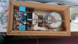
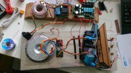
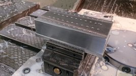
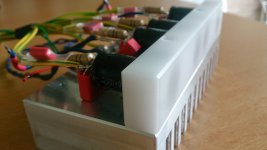
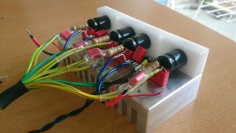
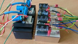
Here you can see the difference between the old "setup" and the new version.
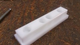
I thought the capacitors where quite a bit fragile, so i decided to make a bracket for them.😱😀
I thought the capacitors where quite a bit fragile, so i decided to make a bracket for them.😱😀
Attachments
-
 DSC_1024.JPG118.4 KB · Views: 360
 -
 DSC_1023.JPG189.7 KB · Views: 341
 -
 DSC_1021.JPG222.1 KB · Views: 239
 -
 DSC_1018.JPG205.2 KB · Views: 246
 -
 DSC_1009.JPG191.5 KB · Views: 569
 -
 DSC_1008.JPG263 KB · Views: 579
 -
 DSC_1007.JPG261.4 KB · Views: 607
 -
 DSC_1005.JPG222.1 KB · Views: 628
 -
 DSC_1004.JPG235.3 KB · Views: 649
Wow. Amazing work.
Any reason not to use a PCB for the gainclone? P2P always looks delicate to me!
Keep us updated with the project.
Any reason not to use a PCB for the gainclone? P2P always looks delicate to me!
Keep us updated with the project.
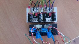
Hi Max,
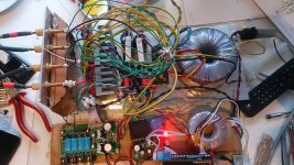
I'm still tweaking it all.
Still not 100% sure how i'm going to fit everything in the case.
Untill i'm sure about that i'll stick with this P2P. But it definitely is delicate.
The heat sink is really just for the mean while. I'll abandon it later. I'll place the IC's directly on the case.
I'm still tweaking it all.
Still not 100% sure how i'm going to fit everything in the case.
Untill i'm sure about that i'll stick with this P2P. But it definitely is delicate.
The heat sink is really just for the mean while. I'll abandon it later. I'll place the IC's directly on the case.
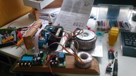
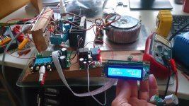
And is that input selector module a PGA23x0 from eBay? Will that and the amp modules go in a single enclosure?
Yup that's an input selector i bought on ebay.
It's not how it's going to stay, I'd really like to use Arduino to control this baby.
Right now this amplifier is dead silent, everything on a glass plate, bad wires and loads of possible interference.
There's just a little tiny bit of 50Hz hum in the output. Probably because the wiring is such a mess.
I really have no noise coming from the PGA2311.
I'm just not sure how i am going to implement the Arduino.
I'm more experienced in the mechanical side of making this amp rather than the electronic side of it.
Please take a look at the rendered picture i've included, it should give an impression of what the inside of the amp will become.
It's just for illustration, I've just drawn a few pockets and a few slots which should be for wires. It's definitively not a final design ;-)
you're looking at the bottom of the amp, it will be covered by another aluminum plate. Making it almost an airtight case. I wouldn't try to throw it in the river, but with a few minor adjustments you can safely do just that! 😎
Attachments

Looks excellent.
One thing I would worry about if it was me: Changing internal components after you've machined the large piece of aluminium. I guess you could always machine the inside larger later. I just find that as projects progress, many of the components change.....so I guess wait as late as possible before milling that massive piece of metal!
You could put the Arduino anywhere. Behind the face, vertical, horizontal, at the rear. A lot of preamps try keep the digital and analog parts separate so perhaps aim for that. Or rather just keep everything that is not analog line level (power supplies, digital parts) far away.
Right now this amplifier is dead silent, everything on a glass plate, bad wires and loads of possible interference.
There's just a little tiny bit of 50Hz hum in the output. Probably because the wiring is such a mess.
When the time comes, give us details on the physical construction so that we can assist in getting rid of the last bit of hum. That assumes you will have any..
We never would have guessed that by looking at that heatsink. 😱I'm more experienced in the mechanical side of making this amp rather than the electronic side of it.
I have two recommendations you should follow.
1. Consider vertical ribs on the sides of the case, they'll cool a tad bit better than the horizontal ones.
2. Do NOT stop. You have no idea how jealous I am of your machining skills and ideas..
Absolutely fantastic job..
jn
Looks excellent.
One thing I would worry about if it was me: Changing internal components after you've machined the large piece of aluminium. I guess you could always machine the inside larger later. I just find that as projects progress, many of the components change.....so I guess wait as late as possible before milling that massive piece of metal!
You could put the Arduino anywhere. Behind the face, vertical, horizontal, at the rear. A lot of preamps try keep the digital and analog parts separate so perhaps aim for that. Or rather just keep everything that is not analog line level (power supplies, digital parts) far away.
This is exactly why i want to get all the internals done first... But on the other hand, it'll give me a second opportunity to make another block if i change my mind after all... haha

I'll really try my best to keep everything as far away from each other as i can. But i don't think that there will be a lot of distortion when there's a thick aluminum wall between the different parts.. If really necessary i could make some copper shields every here and there.
When the time comes, give us details on the physical construction so that we can assist in getting rid of the last bit of hum. That assumes you will have any..
Thanks for the offer, I'm sure i can use some help every now and then 🙂
I have two recommendations you should follow.
1. Consider vertical ribs on the sides of the case, they'll cool a tad bit better than the horizontal ones.
2. Do NOT stop. You have no idea how jealous I am of your machining skills and ideas..
Absolutely fantastic job..
jn
Really nice to hear the kind words 🙂.
The ribs on the side are more for the looks rather than cooling. There's also a small overlap of the front and top. The side is a bit hidden behind it. I've included a view of this.
I'm not really sure whether i'll stay with this design. I have more ideas, and there are two very different styles that i like.
One of them is this one, a bit introvert, slick and classy. A kind of "I don't have to proof myself" design.
On the other hand i'd like some stealth influences; Black anodized, triangular shapes, mean looking. I'll try to draw something soon.
As for the machining, wait till i get really going! I'll be making lot's of pictures if people are interested 🙂
Attachments
- Status
- Not open for further replies.
- Home
- Amplifiers
- Chip Amps
- Introduction and project info