Analog Devices produces a new regulator ADM7151 (adjustable), ADM7150 (fixed voltages) which has better specifications than TI's TPS7a4700.
Actually as far as I know, this is the best performer today.
I'm planning to make some PCBs to test them with my circuits, using the reference design from the datasheet with a couple minor additions (extra cap, resistor+led for indication). And I was wondering if anybody else is interested in it?
As you already know the more we make, less the cost.
Plus, it comes in SOIC package which is diy-friendly.
Here's the datasheet:
http://www.analog.com/static/imported-files/data_sheets/ADM7151.pdf
And some features:
Input voltage range: 4.5 V to 16 V
Maximum output current: 800 mA
Adjustable output from 1.5 V to 5.1 V
Low noise
1.0 µV rms total integrated noise from 100 Hz to 100 kHz
1.6 µV rms total integrated noise from 10 Hz to 100 kHz
Noise spectral density: 1.7 nV√Hz from 10 kHz to 1 MHz
Power supply rejection ratio (PSRR) at 400 mA load
>90 dB from 1 kHz to 100 kHz, VOUT = 5 V
>60 dB at 1 MHz, VOUT = 5 V
Dropout voltage: 0.6 V at VOUT = 5 V, 800 mA load
Initial voltage accuracy: ±1%
Voltage accuracy over line, load and temperature: ±2%
Quiescent current (IGND): 4.3 mA at no load
Low shutdown current: 0.1 µA
Stable with a 10 µF ceramic output capacitor
8-lead LFCSP package and 8-lead SOIC package
APPLICATIONS
Regulated power noise sensitive applications
RF mixers, phase-locked loops (PLLs), voltage-controlled
oscillators (VCOs), and PLLs with integrated VCOs
Clock distribution circuits
Ultrasound and other imaging applications
High speed RF transceivers
High speed, 16-bit or greater ADCs
Communications and infrastructure
Cable digital-to-analog converter (DAC) drivers
Last edited:
PCB for ADM7150
Actually I have purchased 10 pcs ADM7150 and is preparing to make PCBs for 117 and 78xx pinout. Since I don't know how to use PCB layout software, I will go to an electronic shop in Shenzhen (China) in the next few days and ask them to do it for me. I am wondering should I use single side or double sides PCB because double sides cost more than 2 times of single side. What is your opinion?
Actually I have purchased 10 pcs ADM7150 and is preparing to make PCBs for 117 and 78xx pinout. Since I don't know how to use PCB layout software, I will go to an electronic shop in Shenzhen (China) in the next few days and ask them to do it for me. I am wondering should I use single side or double sides PCB because double sides cost more than 2 times of single side. What is your opinion?

I will be using the regulator to drive my DAC that I am using Dexa at this moment. Dexa is excellent but expensive that I would like to try out the differences between Dexa and ADM7150.
The PCB should accomodate the necessary 1uF cermaic and 10uF tantalum through hole capacitors. I don't think I have steady hands to hand solder SMD caps. Do you think it makes a different between through hole and SMD parts? What about making PCBs to accomodate both through hole and SMD parts?
The PCB should accomodate the necessary 1uF cermaic and 10uF tantalum through hole capacitors. I don't think I have steady hands to hand solder SMD caps. Do you think it makes a different between through hole and SMD parts? What about making PCBs to accomodate both through hole and SMD parts?
My plan is to use double sided pcb with smd components. I don't think that you can get away with one side only.
With regs it doesn't make a huge difference if it is through hole/smd.
The major advantage is size.
If you make a pcb with through hole & smd, then what is the point?
But I am not planning to use the super tiny smd parts. I think that for example tantalum caps and 1206 resistors and easy to solder.
With regs it doesn't make a huge difference if it is through hole/smd.
The major advantage is size.
If you make a pcb with through hole & smd, then what is the point?
But I am not planning to use the super tiny smd parts. I think that for example tantalum caps and 1206 resistors and easy to solder.
I am thinking a group buy that if the PCB can accomodate both through hole and smd parts, it could fit diyer with and without steady hands.


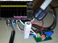
I'm going to add top and bottom ground planes, I didn't do it yet because nothing else would appear in the screencap.
Yes with SMPS. I want to try three different of those that I have and see the results. One is a standard 5v smps for charging my phone, and the other two are 9 and 6v marked as "audio grade".
The plan is to power a buffalo dac and raspberry pi. When Russ White's cap is ready I'm going to switch to that.
I'm going to send today the gerbers for manufacture, I will have them back in about 2 weeks.
The plan is to power a buffalo dac and raspberry pi. When Russ White's cap is ready I'm going to switch to that.
I'm going to send today the gerbers for manufacture, I will have them back in about 2 weeks.
Last edited:
There is a very bead idea to use this chip to regulate the output of a SMPS...
Move the scope gnd lead to the bottom of the load resistor and compare with what you have in picture.
Let's see first if there is enough interest to make it a gb.
I am interested.


Satisfied?
Yes, thank you.
Interesting results. (post 15)
SMPS @ 100uV/div and regulator @ 1.2uV/div.
Cool.
Is there a schematic of your board or is it one from the data sheet?
Last edited:
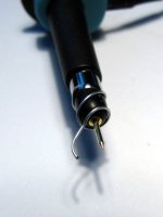
Why use such a high-tech (and high price) regulator and then destroy its performance by using a 3-pin connection ?
Why use such a high-tech (and high price) regulator and then destroy its performance by using a 3-pin connection ?
What would you suggest? The advantage of the 3pin connector is that in some cases you can plug it directly on the target board and in most cases you can place the reg *very* close to whatever you might want to power.
- Status
- Not open for further replies.
- Home
- Amplifiers
- Power Supplies
- Interested in ADM7151 regulator?