Say I am crossing two idealized drivers, at some frequency using LR4 acoustic slopes. Now imagine I changed there acoustic centers so that the distance between them is exactly one wavelength of the crossover frequency. Both would still be wired with same polarity, and sum positively (I think). How would they differ in regards to group delay and step response? Would it matter with driver is delayed: the high passed or low passed driver?
This one cycle jump has happened to me with minidsp. If I remember correctly I could not hear it but it affected distortion and csd near xo. It is easy to test with minidsp or somilar dsp, but I don't have time for it now. Off-axis measurements will show a difference too, best with verticals
Say I am crossing two idealized drivers, at some frequency using LR4 acoustic slopes. Now imagine I changed there acoustic centers so that the distance between them is exactly one wavelength of the crossover frequency. Both would still be wired with same polarity, and sum positively (I think). How would they differ in regards to group delay and step response? Would it matter with driver is delayed: the high passed or low passed driver?
You didn't mention which axis the response is to be evaluated (e.g. on a ray perpendicular to and intersecting the baffle plane midway between the woofers acoustic centers?), and whether the "separation" of the drivers is only in the baffle plane (which I suspect), or also involves front-to-back separation. So, strictly speaking, the question is a little vague.
The relative phase of each source at the listening location determines how two signals will sum. You need an accurate model of the phase response of each driver at its acoustic center AND some way to calculate the phase change that occurs as the wavefront propagates through space to the listening or measurement location. Once you have these well described by a model, you can predict the response, set up different scenarios, and answer your own questions and more.
This kind of modeling of the drivers in the loudspeaker system is done in the Active Crossover Designer. It doesn't give you the step response of the system but there is a plot of the group delay (of the system), which you can compare to limits of audibility from the literature. ACD is the tool I would use to answer these kind of questions.
This is more an idealized hypothetical question. If it helps you can assume coaxial placement, perfectly flat response from each driver.On axis measurement.
This is more an idealized hypothetical question. If it helps you can assume coaxial placement, perfectly flat response from each driver.On axis measurement.
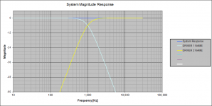
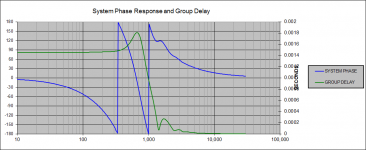
I modeled your hypothetical system using ACD:
- two drivers with "perfect and flat" frequency and phase response
- coaxial placement of acoustic centers
- on axis
- LR4 @ 1000Hz (one driver high passed and one driver low passed)
- system response is the sum of the two drivers
- no delay for either driver
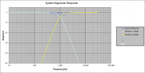
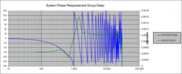
- the low passed driver delayed by 1 wavelength @1kHz = 1 msec = 34.4 cm
- the high passed driver delayed by 1 wavelength @1kHz = 1 msec = 34.4 cm
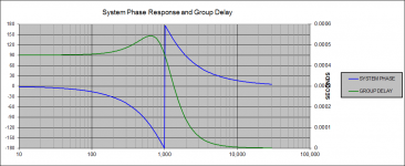
The frequency responses are the same for each case of delay, however, the group delay is different by 0.001 seconds, just as you would expect. The group delay scale is to the right. Sorry if it is partially obscured by the axis label.
Also, keep in mind that there is group delay for the system even for this ideal case and no delay for either driver. This is a result of the LR4 electrical filters, which have their own group delay behavior.
Attachments
-
 on-axis response with no delay.png22.4 KB · Views: 201
 -
 group delay with no driver delay.png23.3 KB · Views: 210
 -
 on-axis response with 1ms delay of LP driver.png47.9 KB · Views: 206
 -
 group delay with 1ms delay of LP driver.png42 KB · Views: 200
 -
 on-axis response with 1ms delay of HP driver.png23.8 KB · Views: 211
 -
 group delay with 1ms delay of HP driver.png45 KB · Views: 109
Awesome Charlie, thanks! I'm most interested in the delayed HP driver, since that is the real world scenario that caused me to ask this. So the character of the group delay is similar, but higher. Too high?
Hi,
In reality you make the LR4 responses asymmetrical
to deal with the actual drivers acoustic offsets to
manipulate the shape of the vertical polar response.
Zaph does it a lot in his designs : Zaph|Audio
rgds, sreten.
Its a purely hypothetical question, no way is an offset of
360 degrees realistic at the x/o point compared to say
offsetting the tweeter back to give 0 degrees at the
x/o point. Group delay consequences are inevitable.
Last edited:
Oops, I just noticed that I reversed the labels on the plots for group delay in my post (#5) above!
The plot labeled "group_delay_1ms_delay_HP_driver" SHOULD READ: "group delay with 1ms delay applied to the low-passed driver".
The plot labeled "group_delay_1ms_delay_LP_driver" SHOULD READ: "group delay with 1ms delay applied to the high-passed driver".
You can tell which is which (without the labels) by looking for the plot that has lots of wrapped phase at higher frequencies. This is evidence of a large delay applied above 1kHz, e.g. to the driver that is reproducing the "high frequencies" e.g. is high-passed.
Last edited:
It's a purely hypothetical question, no way is an offset of 360 degrees realistic at the x/o point compared to say offsetting the tweeter back to give 0 degrees at the x/o point. Group delay consequences are inevitable.
Not so theoretical with eg. minidsp and with higher crossover frequencies! Also some crazy multiway horn speakers will easily break it.
At 3000Hz phase rotates in 0,3ms, 0.11m, 4,5"
Wavelength frequency convert lambda Hz sound conversion acoustics acoustic audio radio measure speed of sound and radio typical waves wave length light vacuum equation formula for frequency speed of light color electromagnetic spectrum - sengpielaudi
- Status
- Not open for further replies.
- Home
- Loudspeakers
- Multi-Way
- Inter-driver delay question